|
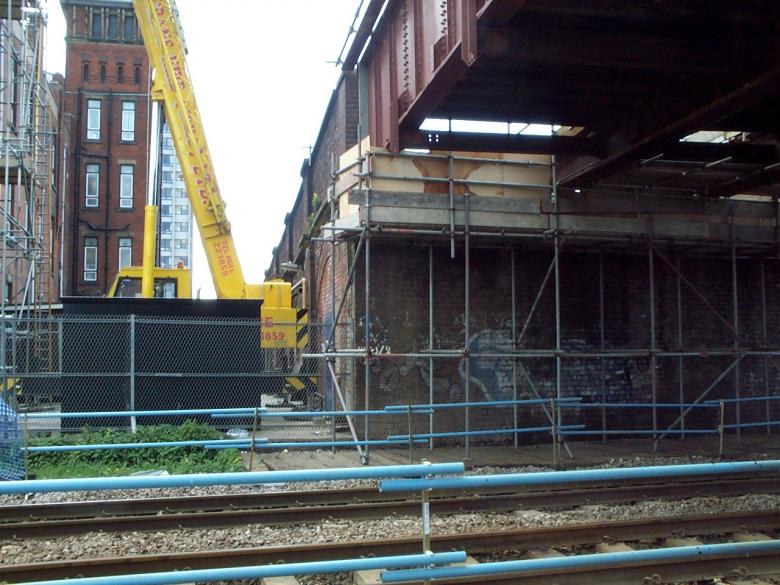
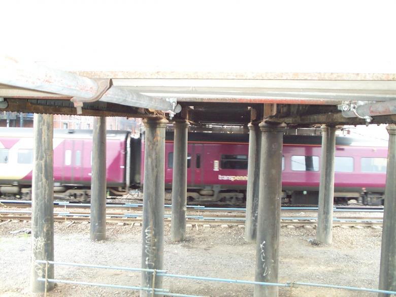
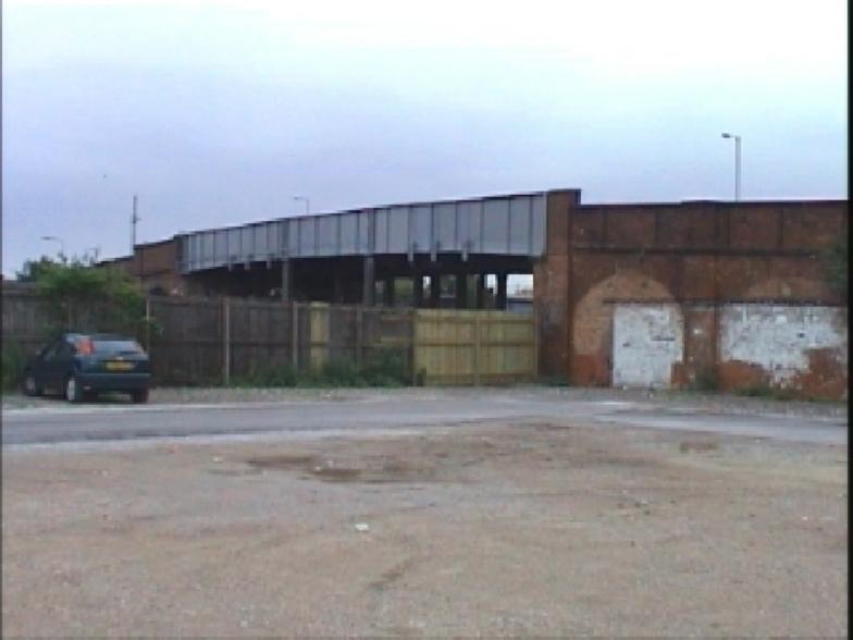
This project involved the refurbishment of Overbridge HUL 1/2 is located 990 yards west of Hull Paragon Station, at track Mileage 0 Miles 990 yards. The Structure carries Argyle street, a single carriageway road and footways, between its wrought iron parapet girders. The road is extensively used by light traffic and pedestrians, it currently has a 7.5 tonne weight restriction. The Bridge is located at O.S. Grid Ref TA 083289. This was the final project worked on by David Millar before leaving May Gurney in the summer of 2002 to move to Alfred McAlpine.
The existing structure was constructed circa 1880 it has twice been considered for reconstruction; in about 1990 and again in 1997. Both schemes were not progressed due to difficulties in obtaining the necessary structural clearances to the track and constraints on the highway alignment.
Argyle Street bridge comprises a three span metal bridge with brick approach viaducts. The bridge carries Argyle street over six rail tracks. Two tracks pass through the North arch brick approach viaduct and carry trains to the nearby Botanic Garden Traction Maintenance depot. Of the remaining four tracks, two tracks run beneath the South (HUL 1 line) and North (HBS line) spans of the metal structure. The short central span of the metal bridge, crosses over the ground between each pairs of tracks.
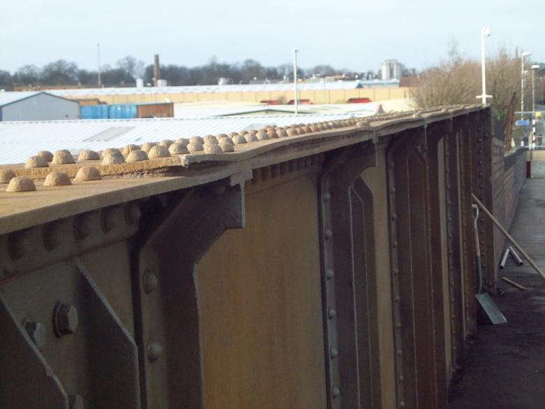
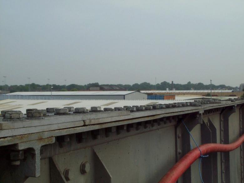
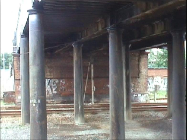
Each of the metal spans comprises five riveted wrought iron longitudinal girders; 2 No parapet girders and 3 No internal girders. Transverse troughing spans between the lower flanges of the parapet girders and is supported on ledge angles on the internal girders. The original troughing is of riveted wrought iron. Large areas of this original troughing have been replaced in the last 20/30 years. The replacement troughing is of rolled steel plate. The north and south spans have a skew span lengths of approximately 11.6m and 11.3m and are skewed at 7deg and 10 deg respectively. The centre span, measured between pier centres varies between 4.8m and 7.6m. The internal girders appear to be in a fair condition, however the webs appear to have suffered loss of section in a number of areas. The parapet girders are in good condition with some surface corrosion. The abutments appear to be in good condition, with no visible signs of bulging, rotation or leaning. The cast iron piers and foundations do not exhibit significant defects from inspection.
The existing structure was refurbished during a series of short possessions and full road closure commencing on site on the 3rd March 03.
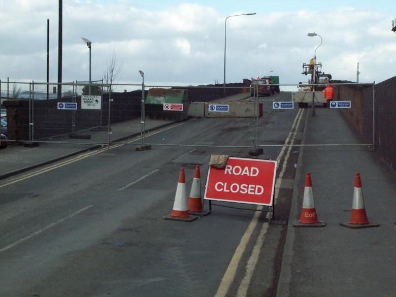
Argyle street closed to traffic and blocked off with TVCB's and Heras Fences.
Following a road closure SYS Ltd erected a scaffold encapsulation system fully covered in with tarpaulin sheeting (the scaffold system is covered by a Form C for temporary works. A timber plywood rebound board is located above the top flange of the top parapet – this prevents any grit and debris falling to track level.
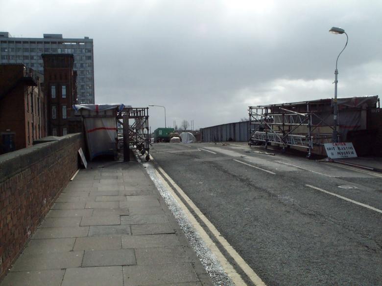
Scaffold blasting frames set up to enable grit blasting to the inside of the bridge main girders.
Jack Tighe coatings set up all blasting lines on the bridge deck blast pots and compressors set up on the deck. Blasting commenced along the parapets, the used grit being collected as the works proceeds, sealed in bags, placed in contamination skip and disposed of to a licensed tip. The grit shall be collected using brushes, shovels, wheel barrows and industrial hoover where required. Following the shot-blasting operation each area was primed with a surface tolerant blast primer. (All works are generally in accordance with Jack Tighe Method statement in appendix E –MS/KE/1066). The blast kettle was fitted with a dead man valve operated by the grit blaster via a handle at the nozzle end of the blast line. Releasing the handle automatically cuts of the grit supply.
Grit blaster wore the following safety equipment: Overalls, Blast helmet, Cape covering the upper body, Gauntlets, Boots, Wet suit, ear- plugs and gloves. Breathing air to the blast helmet will be filtered through a fresh air pack. Only areas that can be undertaken within encapsulation and primed immediately after blasting shall be undertaken such that no bear metal is exposed at the end of the shift.
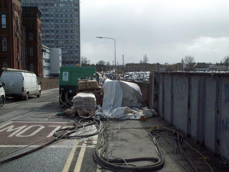
Jack Tighe grit blasting equipment set up on the deck - compressor set with blasting lines.
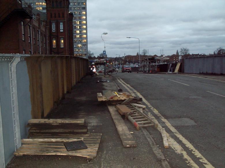
Scaffold blasting frame moved out of the way to enable the waste shot to be removed from the footpath area.
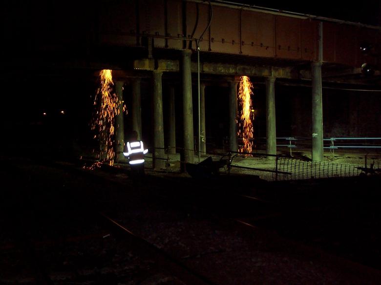
During possession working Jack Tighe Coatings carried out the shot-blasting of the outside parapets, underside deck troughing and columns prior to repainting. Access to undertake the shot-blasting was provided via mobile access platforms running on the rubber mats and sleepers installed previously installed. Polythene sheeting was overlaid and fixed down onto the running mats under any areas being shot-blasted, the sheeting prevented the grit and paint slurry produced from the blasting operations contaminating the ballast. A temporary sheeting system was designed to encapsulate the work zone, this was employed locally to the areas being blasted (i.e. there is little point installing the sheeting system over all the tracks on every occasion as the wet blasting system itself tends to reduce the airborne spread of dust). At the end of the possession the sheeting system was fully gathered in and removed for storage in to the site compound, the used grit was collected as the works proceeds, sealed in bags, placed in contamination skip and disposed of to a licensed tip. The grit was collected using brushes, shovels and industrial hoover where required. The works is programmed such that the shot-blasting work south from the north abutment, initially to open up an area of the steel fabricators to undertake repairs.
Steel-work strengthening
Briton Fabricators carried out the steel work strengthening of the existing bridge structure. The bridge was strengthened with the addition of the following items:
Drawing B4183A/ARG001/CON/005C
-
4nr Bearing stiffeners on each parapet girder A1-A4 & E1-E4. (installation of bearing stiffeners (Possession working only)). Drilling holes approx 200 x 22mm (drilled in normal working hours)
-
Top flange corrosion jacking repairs – approx 700 x 22mm Holes (drilled in normal working hours)
Drawing B4183A/ARG001/CON/006C
Drawing B4183A/ARG001/CON/007C
Britons started the repairs with the site drilling for the installation of the bearing stiffeners A1,A2,A3,A4,E1,E2,E3,E4 and site drilling for the top flange jacking repairs from the 10th March 03. This section of works was not on the critical path thus the work can be undertaken as a stop gap between main repairs. All the holes were drilled during normal working hours.
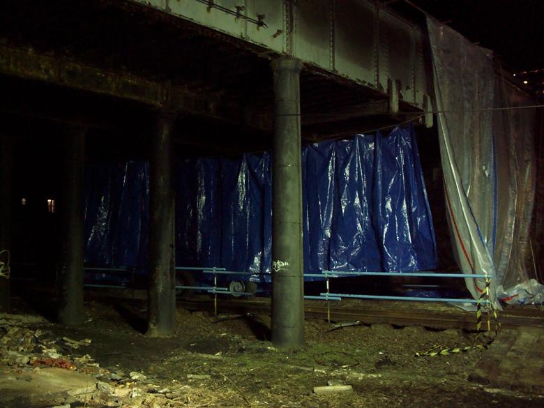
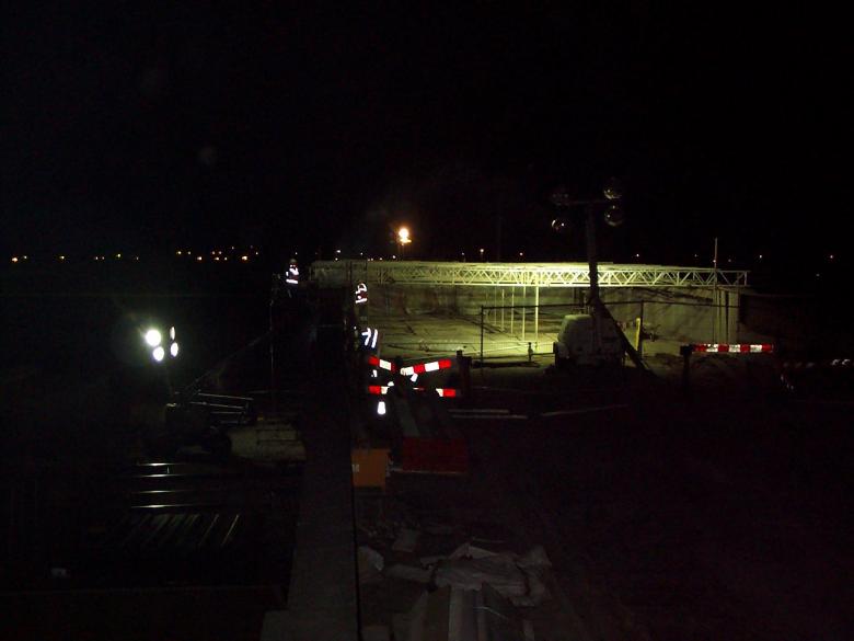
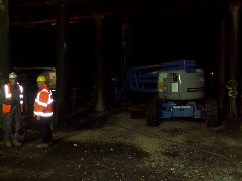
During the night time possessions sections of the track were fully sheeted in with MEWP'S working on the track..
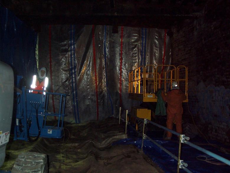
MEWP's working inside a sheeted in area under the bridge.
Painting Application
Spray Painting- Paints to be sprayed by airless/conventional spray machine. Paint will be delivered to a high-pressure gun via a high-pressure spray line with a bursting pressure approximately three times the safe operating pressure. The flow of paint will be controlled by the gun trigger and a guard at the spray tip will avoid allowing the operative using the equipment blocking the tip with his fingers. The paint sprayer will wear the following equipment: Overalls, Gloves, Air fed spray mask (full face), Boots The paint spray machine operative will wear the following safety equipment: Overalls, Gloves, Boots, Fume mask, Goggles, Hard Hat – Breathing air to the spray mask will be filtered through a fresh air pack.
Brush Painting- Paints to be applied by brush will be applied by paint brushes or striker brushes. The painter will wear the following equipment: Overalls, Gloves, Boots, Fume mask, Goggles (if painting overhead), Hard Hat
Roller Painting- Paints to be applied by roller of appropriate diameter. The painter will wear the following equipment:Overalls, Gloves, Boots, Fume mask, Goggles (if painting overhead), Hard Hat
Inside Parapets and top flanges – apply paint in accordance with Railtrack RT98 M20 Specification following blasting and steel work repairs.
Outside Parapets, underside bridge troughing, columns and new steelwork – apply paint in accordance with Railtrack RT98 –Copon Hycote 152LV paint system following blasting and steel work repairs. Paint manufactures instruction regarding overcoat and curing periods will be followed
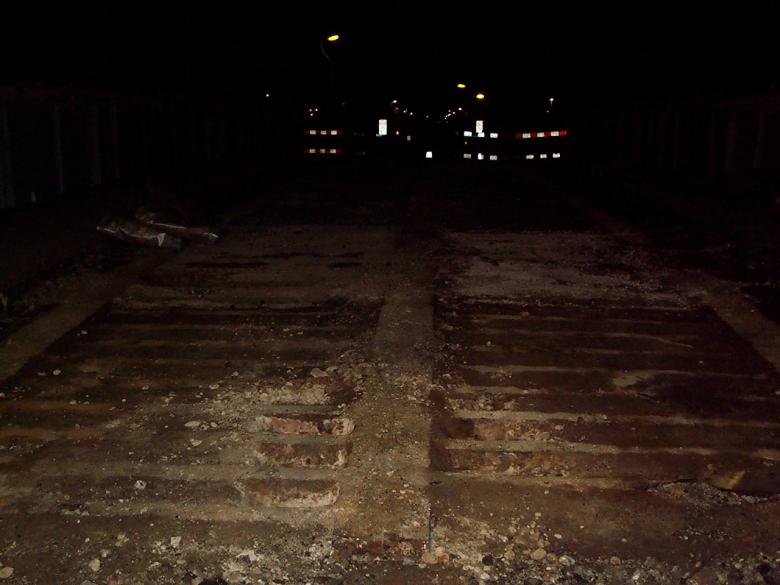
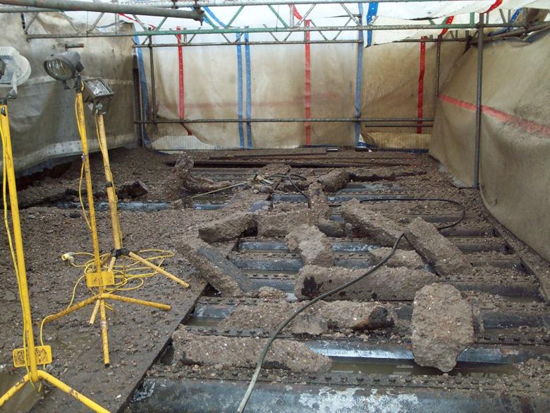
The bridge deck surfacing was removed to expose the deck plates.
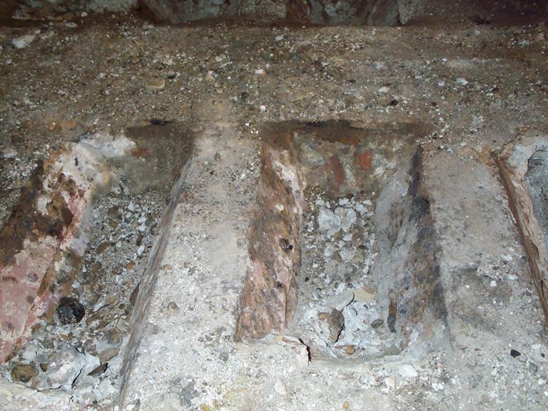
Concrete in the troughs - not reinforced reasonably weak material.
May Gurney operatives are to erect debris screens created from Heras fence panels – plywood and monoflex sheeting. This was later extended by SYS ltd who installed a full scaffold screen - tented area which was moved across the structure as the hydro demolition was undertaken and completed on a section of the deck. R.H. Buxtons set up a 5000 gallon water bowser and connecting up to two pressure jetting units. Two operatives are to control each unit working across the bridge deck blasting free the concrete from the troughs from one parapet to the other. The Hydro demolition was progressed across the bridge - clearing the concrete from the trough routes. The troughs were found to be in very good condition over the majority of the bridge deck. The Hydro-demolition was undertaken during T(II) T Night shifts (typically 5hrs long) David Millar carried out the duties of the COSS during the course of the works - using TCODs to set up the protection (Track circuit operating device) - Jump leads by another name !!
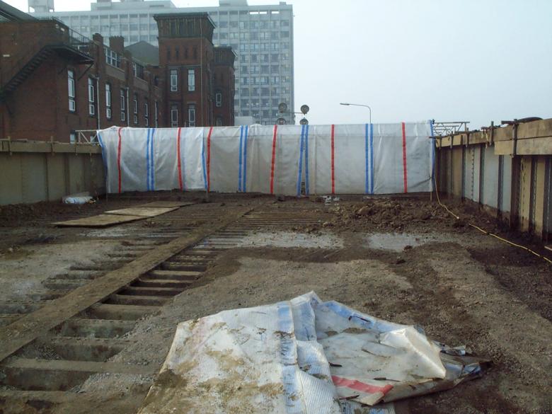
A scaffold enclosure was constructed over the structure to enable Hydro-demolition to be undertaken during normal working. Note the cable protection timbers on the outer girders.
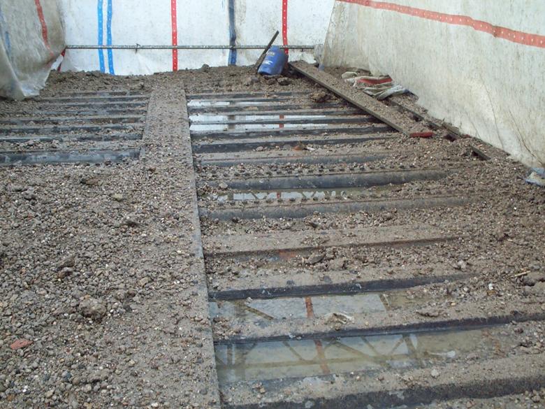
Buxton Ltd carried out the hydro demolition clearing out the old concrete from the deck troughs.
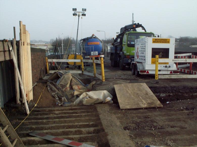
Buxtons hydro-demolition rig and bowser water supply parked just of the bridge.
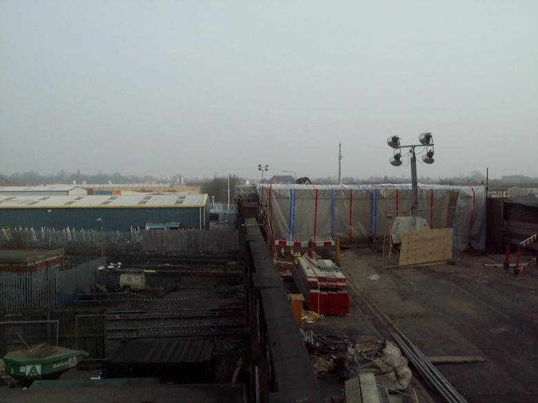
View over the bridge deck lokking at the scaffold enclosure erected by South Yorkshire Scaffold (SYS Ltd).
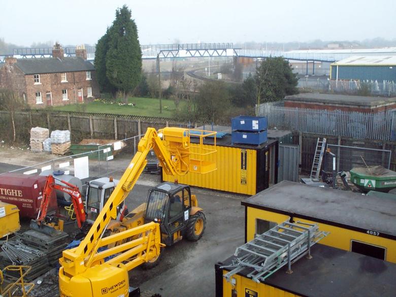
May Gurney site compound in the Car Park of the Hospital - David Millar site office with the blue stillages on top.
Due to the force of the Hydro- demoltion - works were shifted to night shift.
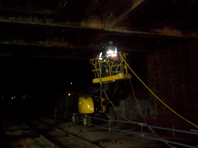
Briton Fabrication started steel work remedial repairs to the bridge from a MEWP.
Hydro - demolition in progress - nights work - steel blasted clean.
Britons utilised a small crane to lift out troughing to gain access to carry out repairs to the main girders. Access to cut the troughs was from deck level with operatives using burning gear. As the troughs were removed edge protection was provided across the deck - walkways were provide across the deck to give access. The crane set up and lifted from both abutments - with the troughs being stacked up ready for removal - Britons carried out the fabrication of new deck trough units ready for installation once the repairs were completed.
Britons cutting sections out the deck to enable access for steel work repairs.
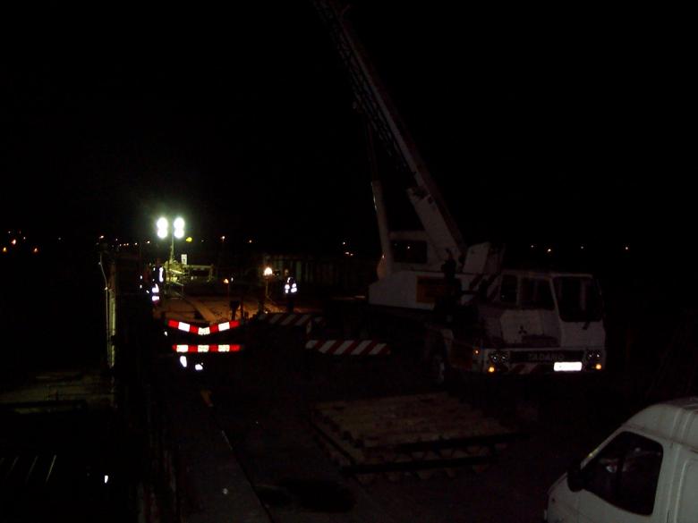
Crane set up to enable the deck sections to be lifted out for access.
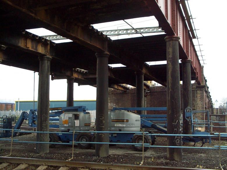
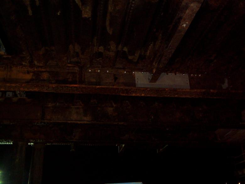
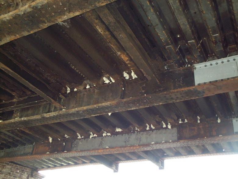
View on the underside of the structure with holes cut in the deck for access for the steel work repairs.
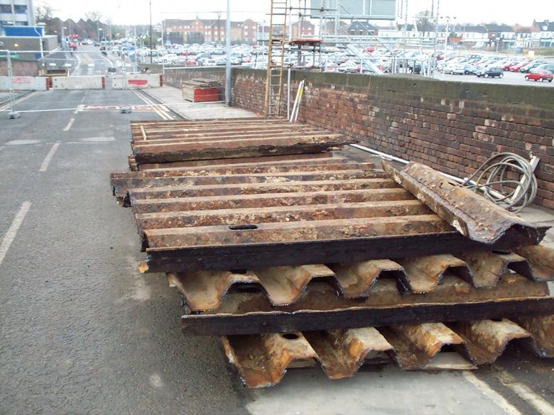
Old trough sections cut and stockpiled on the approach to the bridge ready for removal - these are to be sent for scrap.
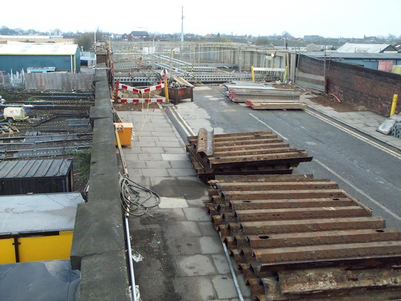
Scrap trough stockpiled on the deck ready for removal works on the deck temporary works underway.
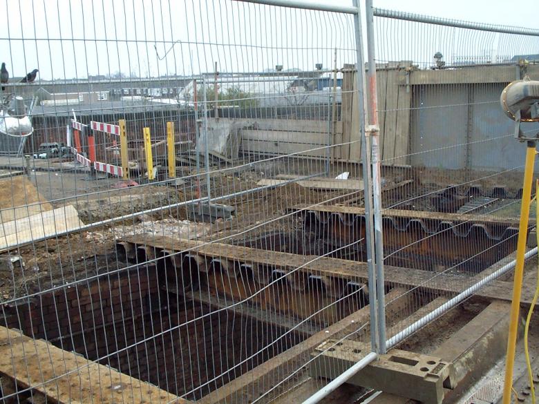
View on the deck end access holes cut open.Trough section require cut away to allow the repairs to be undertaken.
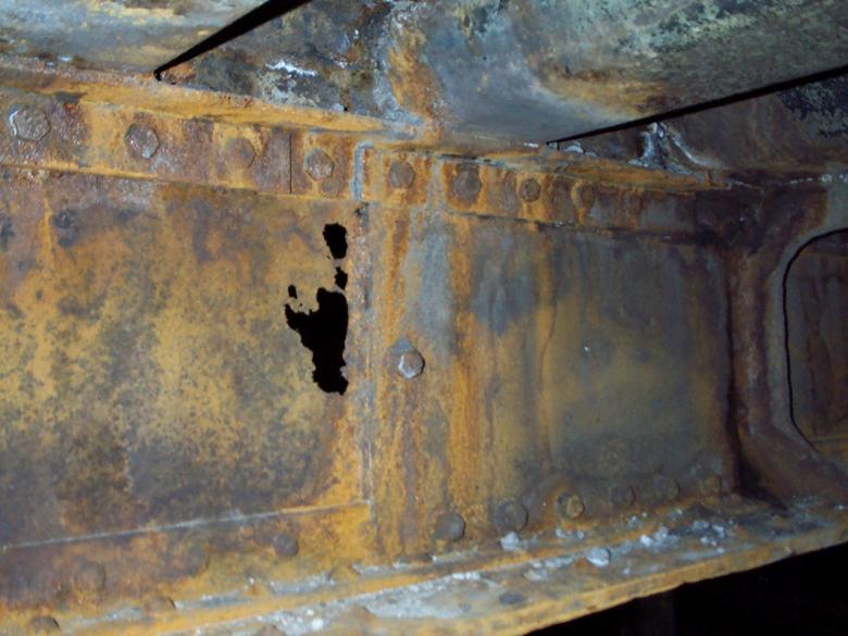
Typical view on areas on the girders that have rusted through. (This view shows an old repair over the girder)
On removal of the troughing May Gurney operatives installed a temporary working platform created from RMD soldiers. SYS created a tube and fitting scaffolding working platform to gain access to each repair area. The working platform was designed such that no part of the temporary works encroached within the minimum clearances required for the standard gauge railway in accordance with GL/RT 5204. The outline of the RMD/scaffold did not interfere with any of the signal sighting distances. None of the working platforms are located directly above the tracks. Mobile access platforms were used during the possession to enable the scaffolders to easily access the work areas to install the tube, fittings and boarding. Following the installation of the working platforms each section was given an identity reference number to enable it to be recorded in the PUWER register and a “scaff-tag” showing the scaffold identity and record of checking. The scaff-tag system will be used to demonstrate that the scaffold has been inspected each week and weather or not it’s fit for use (where the “scaff tag” is coloured red). Only trained/ experienced scaffolders in accordance with the requirements of BS5973 are to carry out erection and alteration to any scaffold.
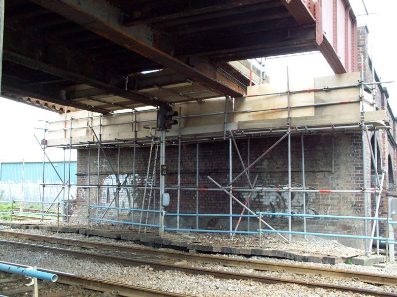
Access Scaffold installed to the West side of the structure to enable repairs to be undertaken during normal working.
Scaffold being installed to the East abutment to enable works to be undertaken. The crane working in the Hospital grounds was being controlled by Network rail - Roy Ashforth site manager.
During possessions scaffolds were erected (hung) to provide access to the repairs in the centre of the deck.
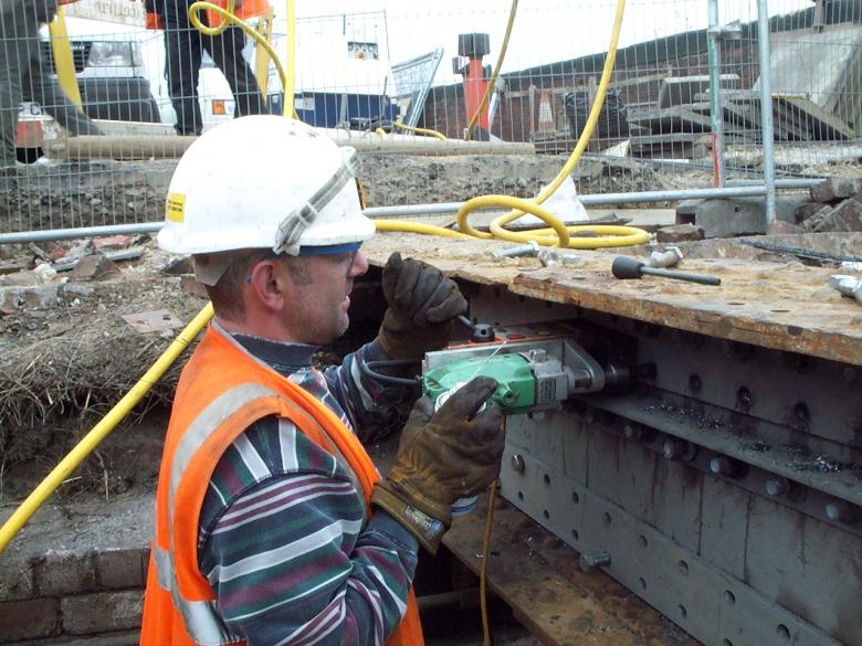
Britons Fabricators - installing anagle plates and doubler plates at the abutments - the angle being fixed is designed to carry the new section of troughing.
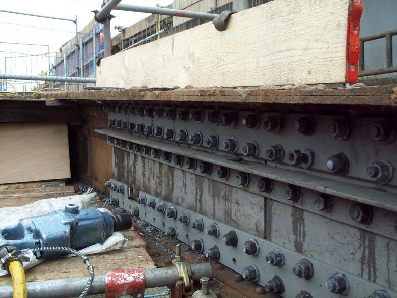
Steel work repairs to the abutment steel. New bolts being tightened up to hold the angle sections and doubler plates together.
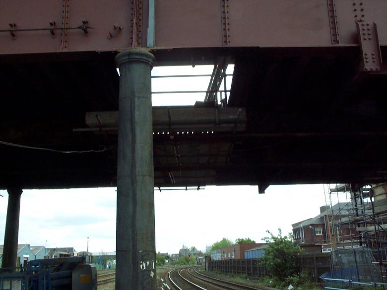
A view looking across the soffit of the bridge. The clearance for the bridge is 4m (David Millar measured it and it was bloody tight)
Working in possession carrying out the steel work repairs to the girder flanges.
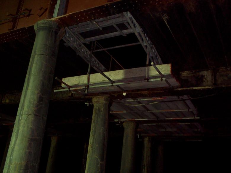
View on the scaffold hung from the RMD's on the bridge deck.
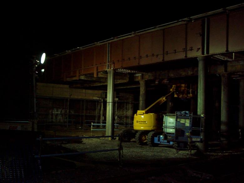
Grit blasting and painting resumed on the bridge - Hewdens fitter carried out running repairs to a crippled MEWP.
May Gurney Senior Foreman Terry Loney on site during the painting and steel work remedial nightshifts.
On completion of the steelwork repairs and installation of the ledger angles the troughing is to be installed was undertaken using a small crane.
On-site trough fitting procedure (8 positions at bridge abutments (central area similar but obviously sits on the existing trough not on the abutment) (in possession working)
Install long section of trough. This is supported on abutment, ledge angle and existing trough. Where material needed to be cut-out from the troughs around bridge stiffeners on girders A and E this is to be done locally on site as required. Where required the troughing was packed to the required level on the abutment end using a temporary angle. The short piece of trough section were slid into position. This is supported on 10mm thick pads pre-welded onto the end of long section, existing trough and the ledge angle on the opposite beam. With the troughing units aligned 10mm thick pads were welded (supplied loose) on each flat position where the trough sections join, weld is to be 6mm fillet. With the troughing set into location the temporary angle can be removed.
New sections of steel fabicated trough installed and sealed up to prevent grout loss during the concrete pour.
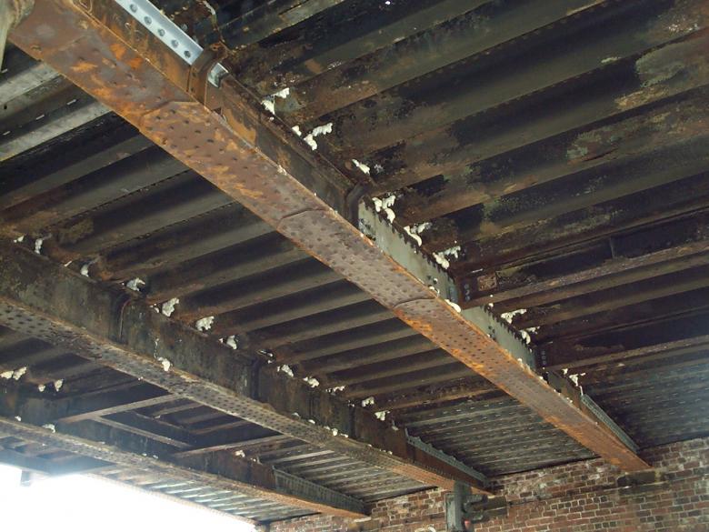
View on the soffit of the structure following steel work repairs and new trough installation.
May Gurney operatives used Plastiseal joint sealant (by Fosroc) to fill in the joints between the existing deck trough and central girders. The plastiseal was gun grade and type gun applied from bridge deck level. Where the holes are over 40mm wide a steel fabric mesh is to be compressed into the gaps to enable the plastiseal material close the gap. Sand cement (+sika 4a) material to be used to block up the gaps greater than 40mm. Expanding foam is to be used at the back of the trough/girder interface to act as a secondary barrier to grout loss during the deck pour.
Once ready the bridge deck was jet washed and blown out prior to steel fixing. Steel fixing to the bridge deck commenced on the north abutment working back across the deck as areas become available after trough replacement.
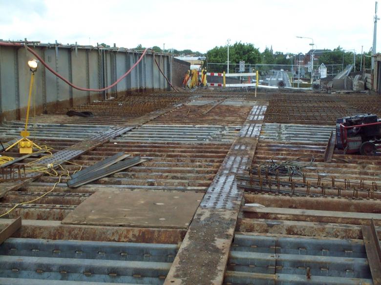
New trough installed view on the bridge deck - steel reinforcement being fixed by Cairn cross Civil Engineering Ltd.
During the grit blasting during the early days of the project identified issues with the top flange doubler plates.
New Doubler and triple top splice plates added as replacement for the riveted doubler.
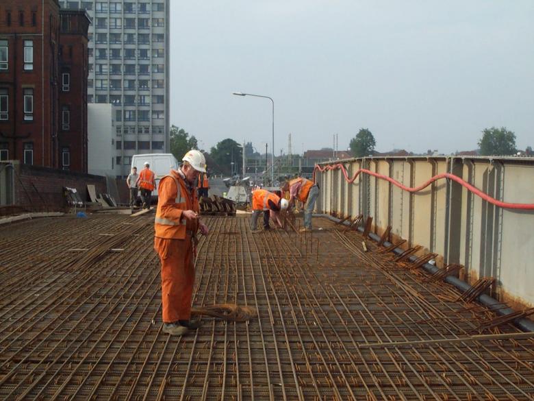
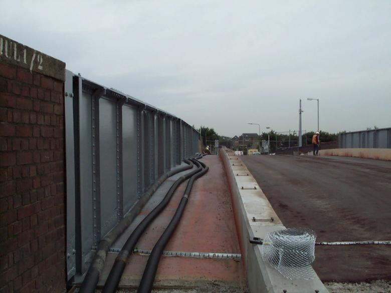
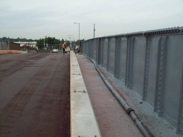
Steel fixing on the bridge deck . Note teh 11kva Cable attached to the inside of the outer Girder.

Steel fixing on the bridge deck well underway - kicker being fixed across the deck. Note the services suspended of the girders and the hospital in close proximity.
11Kva cables being connected up just of the bridge to remove excess slack installed at the start of the project.
Concrete Deck Placement.
On completion of the steel fixing timber stop ends are to be constructed on the abutments and proprietary drainage channels fixed into the deck ends. A May Gurney supervisor supervised exclusion zone is to be set up under the bridge structure to prevent unauthorised access during the abutment repairs this will be done by a COSS. Concrete placement was undertaken during a T(ii) a protection of the lines. Prior to the possession a concrete pump is to be located behind the east abutment ballast wall where it’s boom can reach the full extent of the bridge structure. A second concrete pump will be available on stand by, however the concrete pump will not be on site. During the concrete pour – due to the condition of the superstructure a May Gurney supervisor is to monitor visually the existing structure for signs of distress and also for any areas of grout loss (this was anticipated as the structure and troughs are holed). A mobile access platform, operator and joiner were available to carry out remedial action to stop grout loss. The concrete was compacted using a series of compressed air poker units and levelled using screed rails and a beam-tamping unit.
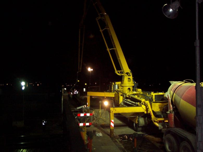
Due to the poor condition of the existing structure and extensive steel work remedials - the concrete pour was undertaken during a T(iii) Saturday night possession.
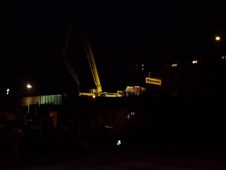
View from the site compound looking up to the bridge abutment as the concrete placement progresses.

The bridge deck cast with North upstand parapet being set up.
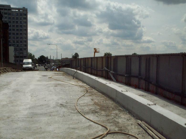
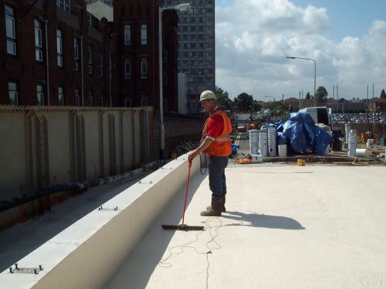
South parapet upstand aleady cast with bolt clusters set. The bridge deck being scabbled and prepared for spray waterproofing.
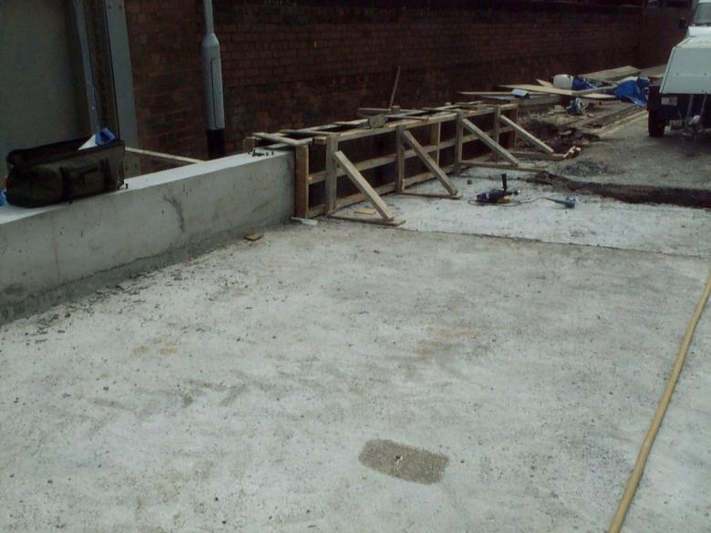
Concrete upstands being constructed of the end of the deck + pull off tests being undertaken note the test.
Spray applied waterproofing - eliminator waterproofing applied by Waterseal limited - Note the pull off tests above and the spark testing in the photograph below.
May Gurney operatives carried out surface preparation to the concrete deck following completion and curing of the concrete deck and up stands. The concrete requires to be free of all oil grease, curing compounds, shutter release oils, loose particles, latencies, friable material and other contaminants. The Bridge deck was inspected by May Gurney and Waterseal post concrete placement. The concrete deck was spot tested for adhesion. On satisfactory completion of the tests May Gurney authorised Waterseal to proceed. A May Gurney supervisor masked off all areas prior to overspray protection. May Gurney provided a compressor to supply air for the spray rig. Two part polysulphide was applied over the bonding tape along the deck rebates. The sub strata was primed with Stirling Lloyd primer PAR1 at a rate of 0.2-0.25kg/m2 and allowed to cure. The steel parapets were primed with ZS94 Primer at a rate of 0.2kg/m2. The membrane was applied in one coat as per manufacturers specification at a rate of 2.8kg/m2 to give a minimum thickness of 2mm over peaks, arrases and irregularities. The wet film thickness shall was checked every 10m2 using a standard type comb.
Spray waterproofing - spark testing to the deck.
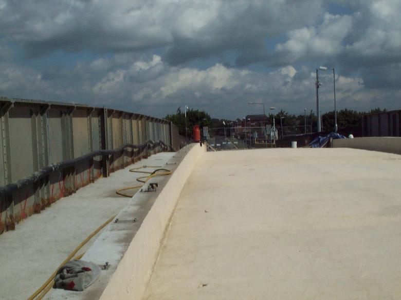
Waterproofing on the bridge and up the upstands.
Ekspan drainage slotted channel set and fixed into position with Epoxy.
May Gurney / Cairn-cross Construction operatives completed the installation of the deck drainage system installing the galvanised honel drain system at the deck ends with CW1 resin.
On Monday 16th June 03 PBS (Lane Rental) Ltd laid the red sand carpet on the bridge deck between the new bridge parapets. The water proofing had a tack coat applied to ensure a good bond between the waterproofing and the sand carpet. The coloured bituminous coated macadam and asphalt’s are to be produced in an off site batching plant and delivered to site in insulated tipper wagons with the load being covered to minimise heat loss.
The main plant and equipment for the sand carpet is to be delivered to site at the start of the shift. The approach roads were available for PBS to store plant and equipment as well as undertake preliminary works for Hull city council i.e. lift drainage manholes, clean out gullies etc – their work for Hull City Council is not covered by this method statement, however details have been included for information purposes.
The red sand carpet was laid using a mini paving machine and compacted using a 10t deadweight roller without leaving any defects or irregularities. The sand carpet was levelled to record the material use and checked by both PBS and May Gurney supervisor.
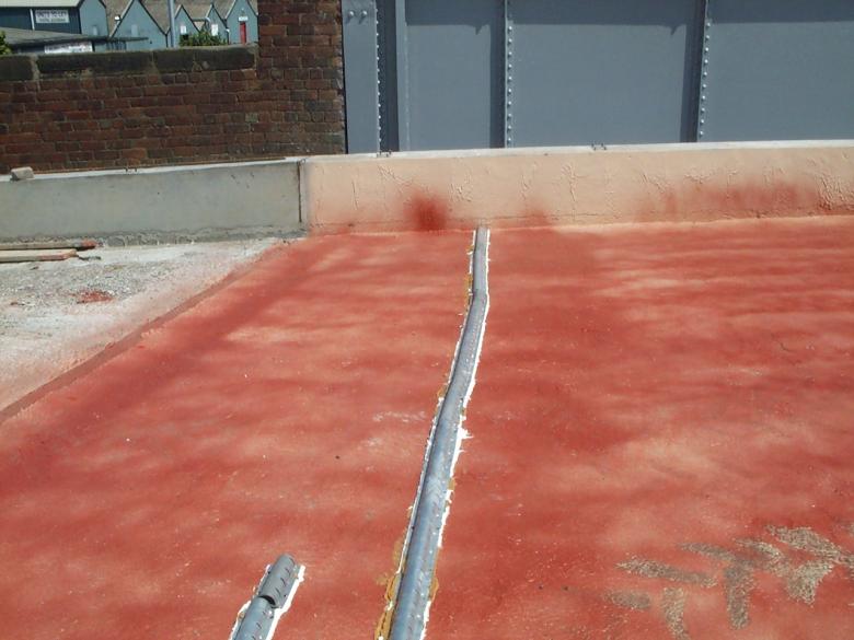
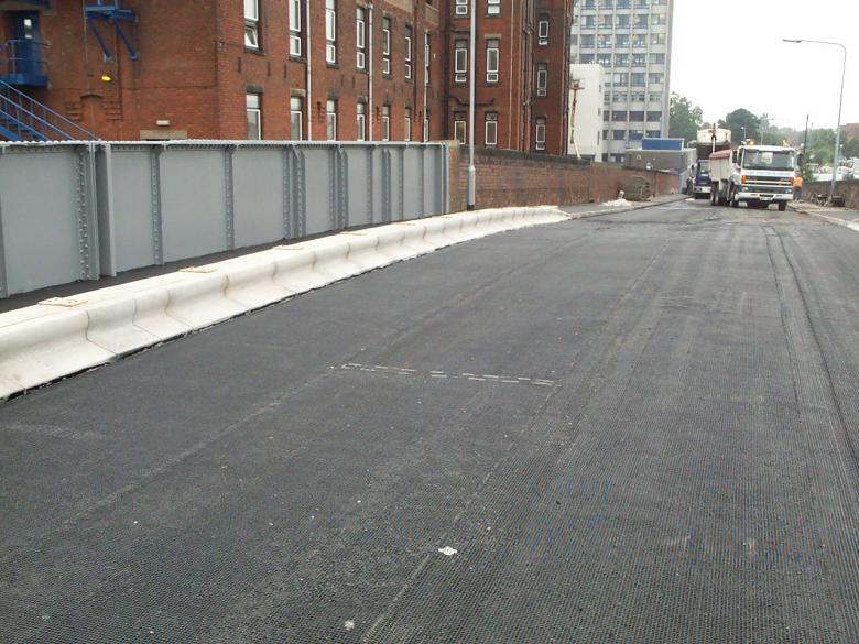
Red Sand Carpet laid on the bridge deck to demarcate the spray waterproofing.
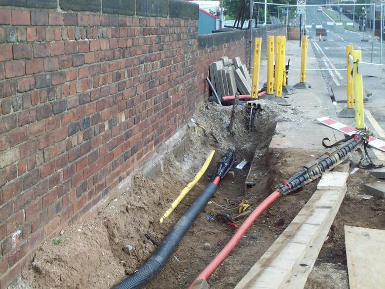
Spray Waterproofing in the footpath - services in ducts running across the bridge.
Lighting cable in duct in the footpath.
Road Construction (Kerb alignment)
May Gurney and Cairncross Ltd removed and realigned the existing approach kerbs either side of the bridge abutment. These kerbs were broken out using a compressor and hand held breakers. A mini digger was used to dig out the existing kerbs after cutting with a diamond bladed cut off saw.
The New Kerb line wass installed to the contract drawings, however since the drawings do not represent the true alignment of the existing road kerbs to bridge deck – May Gurney asked Hull City Council to provide details of their requirements for the kerb tie in’s (the bridge deck is 6.4m wide the approaches are 6.6m wide (i.e a 200mm realignment required). Hull City Council provided a site based clerk of works to oversee the road construction and to ensure that the road alignment, kerbs and footpath are to the required standard for adoption. May Gurney and Cairncross Ltd installed the new terif kerbs on the bridge deck utilising a forklift and proprietary block grab supplied by La Farge.
The Kerbs were laid on ST2 concrete placed from the back of a mini concrete wagon (3m3 capacity). Concrete was also to be placed in the footpath to below wearing course regulating level. Suitable overalls, goggles, gloves and Wellington boots were worn during placement and compaction of the concrete. Two empty ducts are to be installed on the bridge footpath to carry future services – the ducts were installed on the west footpath as per the contract drawings. YEDL reinstated the street lighting columns on Thursday 19th June 03
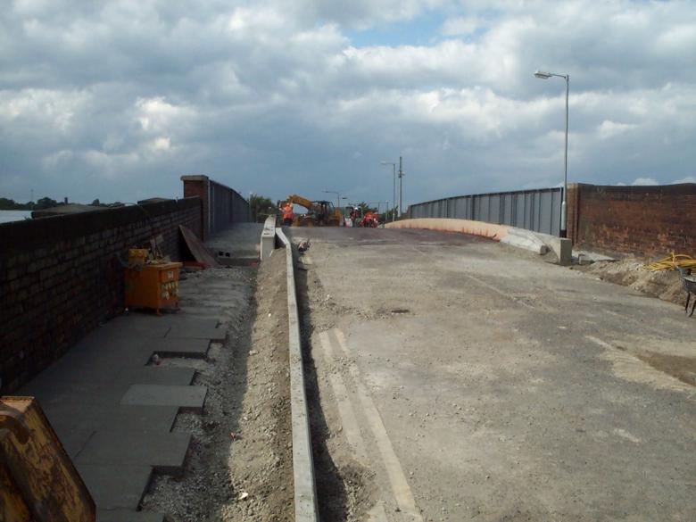
Kerbs being installed on the approach to the bridge - Note the larger kerbs against the parapet upstand.
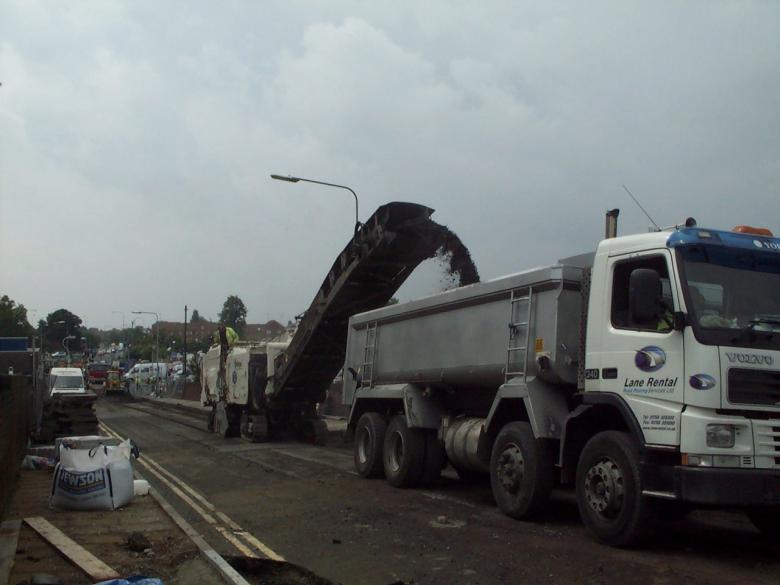
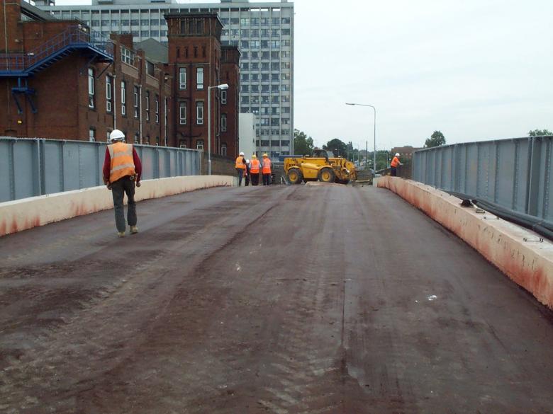
Road being cold milled on the approach to the bridge.
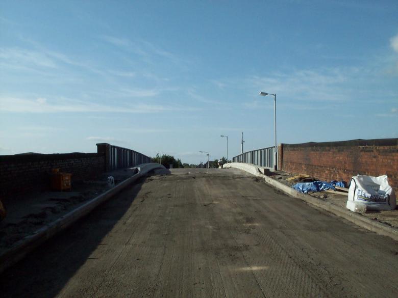
Road fully planned out ready for new road base and surfacing.
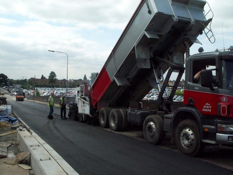
New surfacing being laid on the approach to the bridge deck.
Surfacing being laid over the bridge.
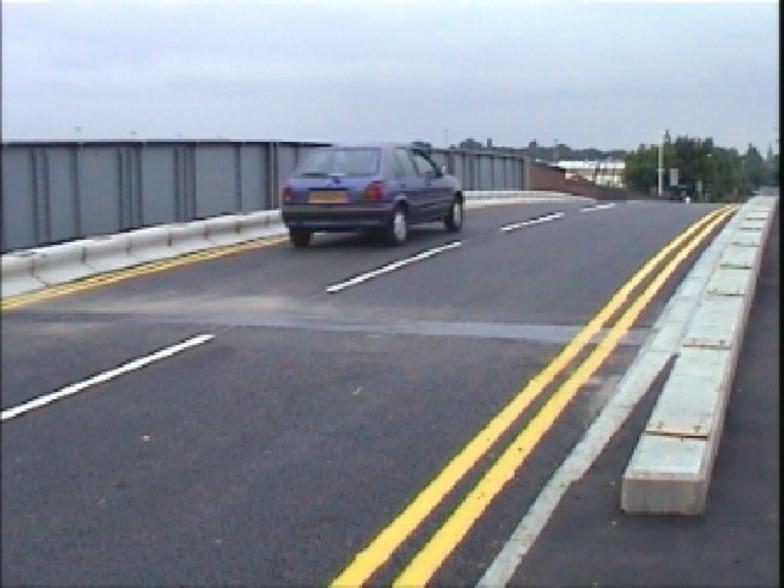
Bridge open to traffic - Bridge plug joints installed by USL. New Parapets on order but not installed.
May Gurney site compound removed - new fence installed - bridge fully painted.
View on the underside of the bridge - the bulk of the structure being painted - Columns however were not painted.
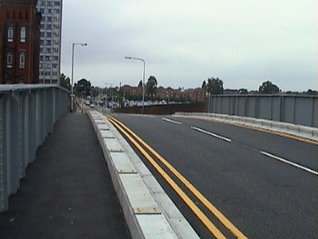
View on the footpaths and bridge deck - pedestrian parapets still to be installed.
.
| 