|
This project involves all works required to undetake a railway underbridge replacement in a 53hr railway possession during the summer of 2002. This project highlights the importance of good planning and especially taking time to evaluate the feasibility options to identify the best way to take a project forward even when options appear not to be available or obvious.
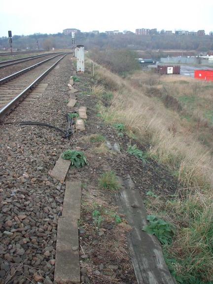
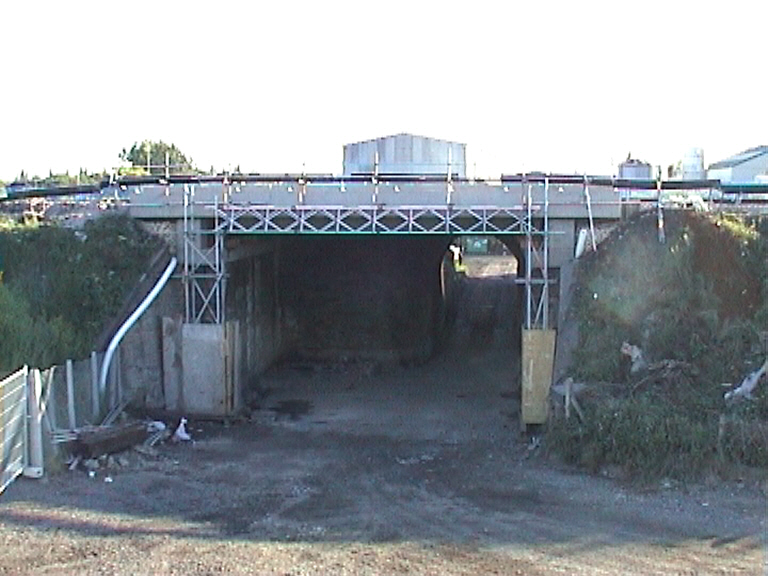
Original structure description - Underbridge CTL3 is located between Calder Bridge Junction and Turners Lane Junction, Wakefield, at track Mileage 0 Miles 198 yards. The structure carries the Up and Down CTL Lines over a private access road to the Calder Vale Waste-water treatment works, owned by Yorkshire Water Services (YWS), and a licensed tipping facility (managed by Biffa Waste Services). The Bridge is located at O.S. Grid Ref SE 344 200.
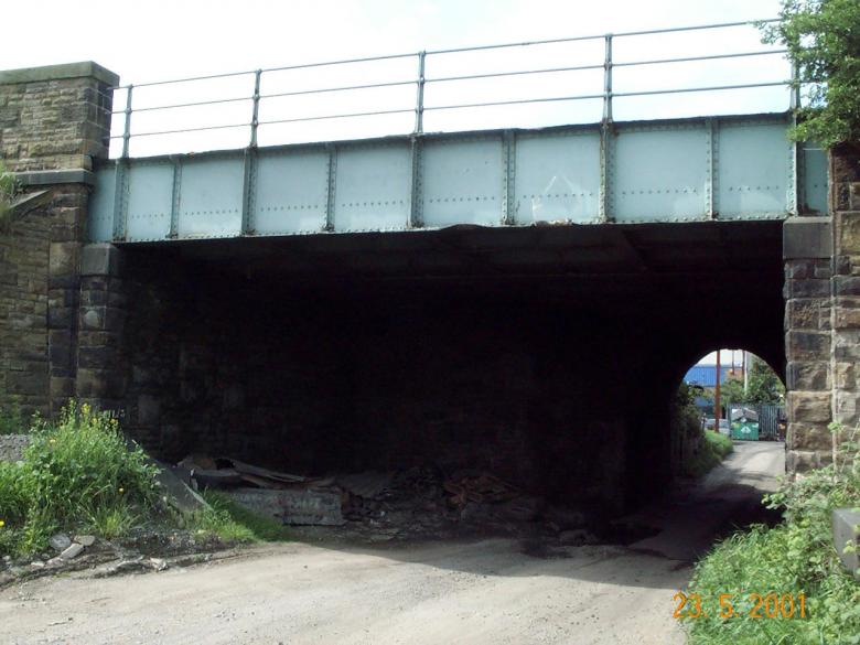
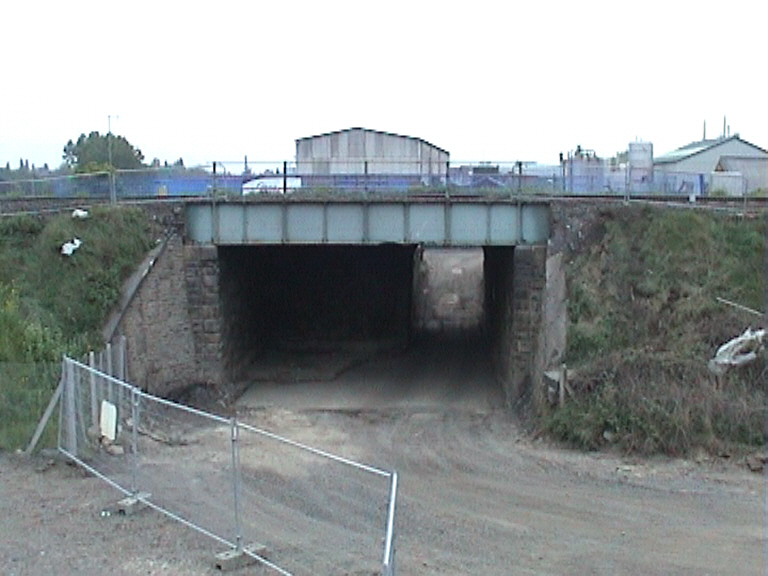
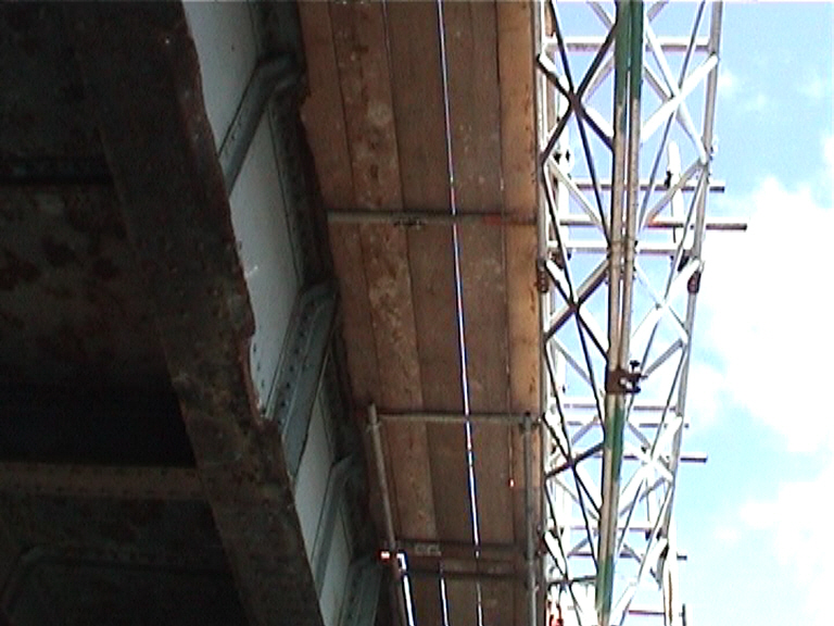
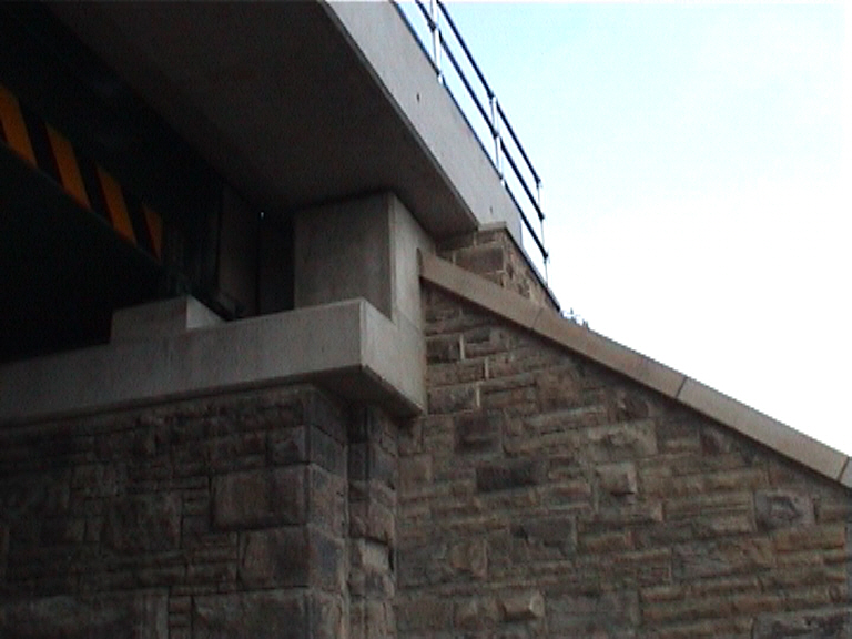
View on the existing structure.
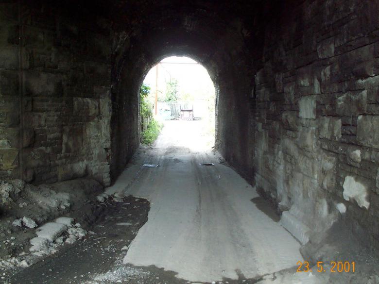
View on the existing road way under CTL3.
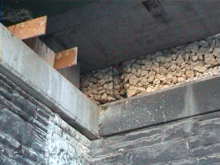
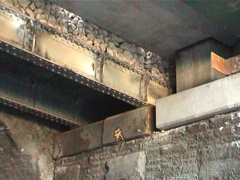
The structure was constructed in 1895 and had a 10.25 metre span. The half-through steel underbridge comprising three main riveted plate girders with cross girders and rail bearers supporting a steel plate deck. The structure carried two ballasted tracks. The railway runs on embankments on the approach to the structure. The minimum headroom was 4.223 metres (central girders) (before modification). The structure is located immediately alongside underbridge WAG 1/3, a 3.58 metre span red brick arch underbridge carries the Up and Down Goole lines. The top flange of the existing main girders was found to be severely corroded with several localised areas heavily corroded back to the web/flange angles. The abutments (retained as part of the new structure) were found to be in good condition, with no visible signs of bulging, rotation or leaning.
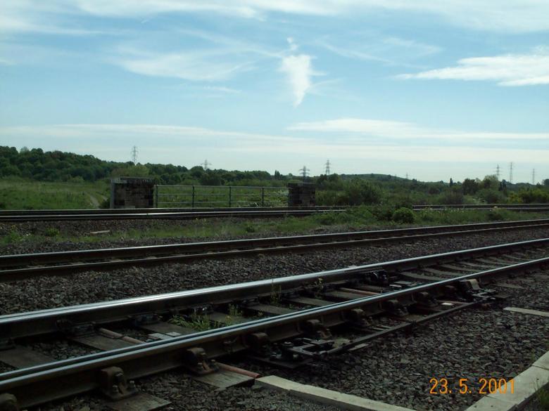
View over the track bed. Looking toward the CTL3 parapet.
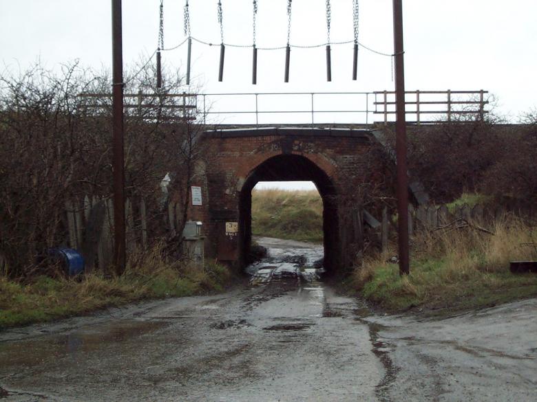
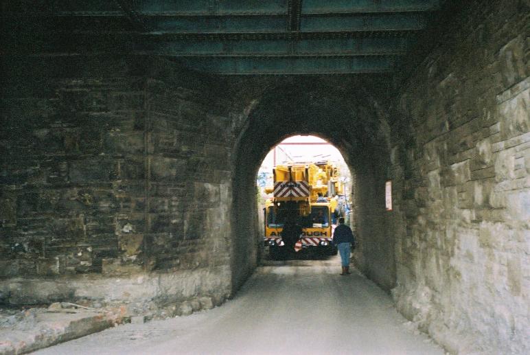
View on access under the WAG line passing through to CTL3.
View along the embankment - cable route
An initial feasibility study prior to David Millar starting on the project looked at the replacement of the structure using heavy crane (800t - 1000t) and also looked at using multi-axle to remove the structure. A third option of using a smaller crane (400t -500t) located on the water treatment works side structure was ruled out, as the only access was under the WAG 1/3 arch and CTL3 structure. This access was deemed to tight even for this size of crane.
During December 2001 with MVL3 -81 Nearing completion - David Millar moved back to the York project office and started looking at the planning of the CTL3. Extensive work on feasibilities had been undertaken looking at the best way to replace the bridge however following a site visit in mid December 2001 - David Millar carried out a number of trial holes infront of the abutments to evaluate if it would be possible to reduce the ground level under the bridge and hence make access for a large crane possible.
Following a full review of the options it was identified that if the ground level under the structures was reduced it would be possible (with a few bits of the crane removed !!) to pass a 400/500t crane through the arch.
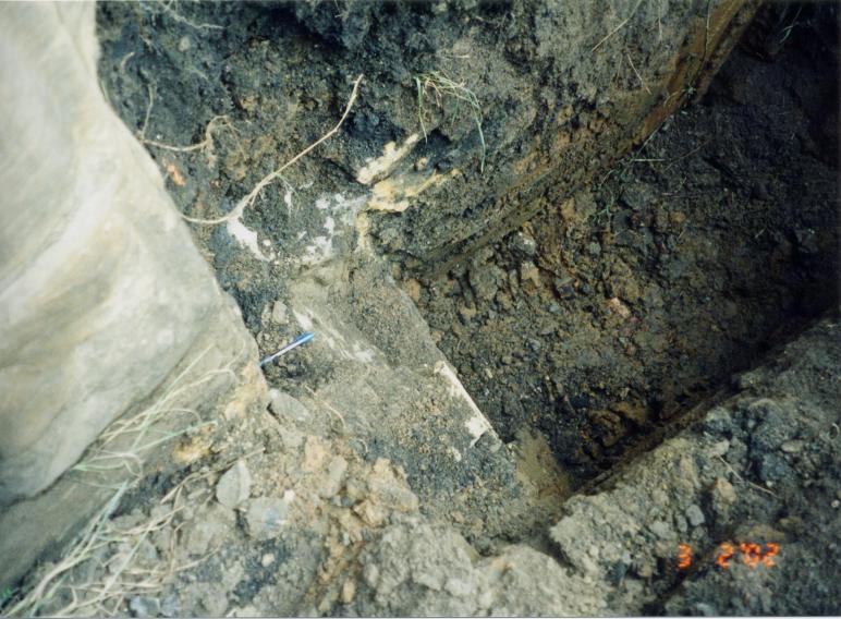
Trial holes excavated under the bridge to review the potential for dropping the road level under the structure.
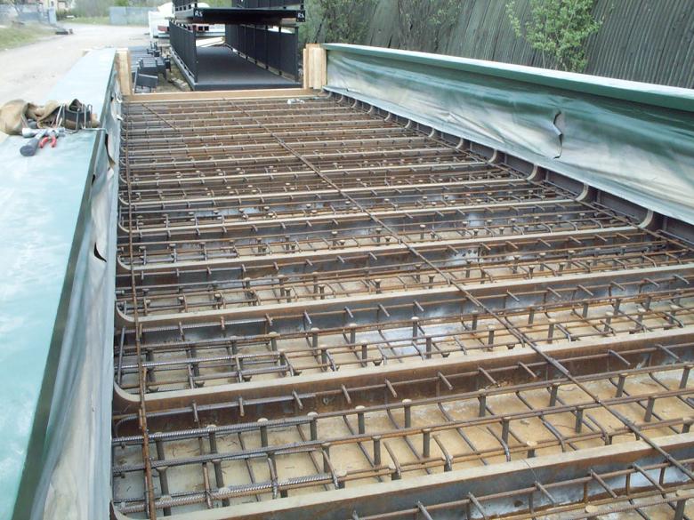
The new bridge units were fabricated by Britons Fabrication limited and shipped to Jack Tighe's in Doncaster for painting. Following painting works David Millar approached Jack Tighe about casting the concrete to the bridge deck in the yard - as the access to the site was not available until after the Easter bank holiday.
Bridge - painted in the Yard at Jack Tighe Doncaster. - The bridge deck fabricated by Britons.
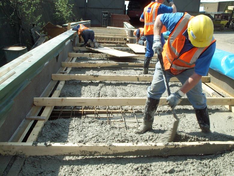
Bridge deck being concreted in the Yard by May Gurney.
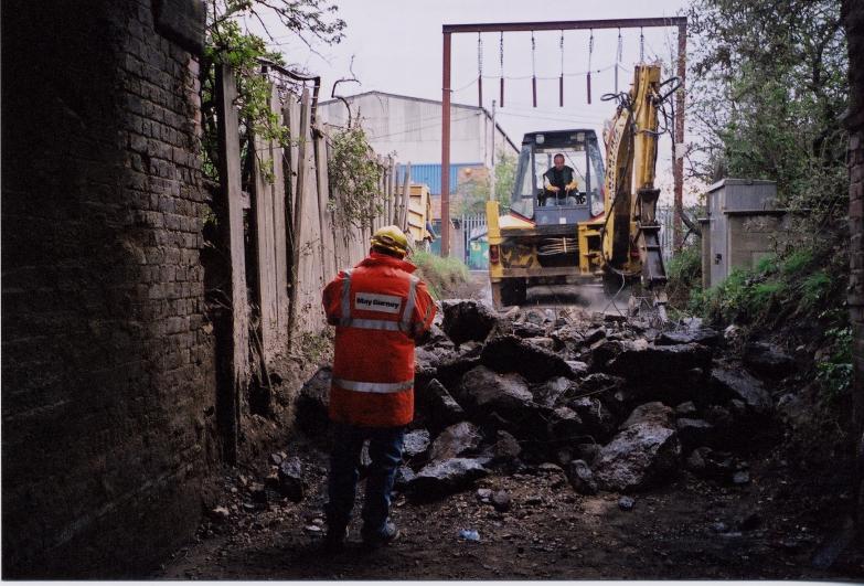
May Gurney breaking out the existing route under the bridge to deepen up the road way for access.
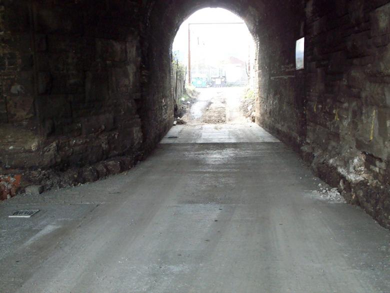
New road created under the existing bridge.
New concrete slab installed under the structure - New drainage set up.
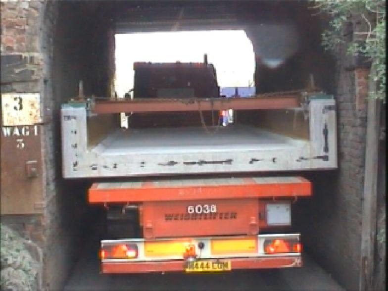
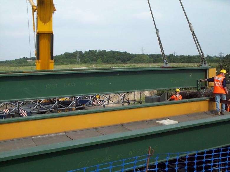
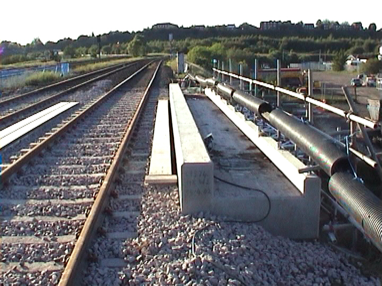
The structural form was completed with two precast concrete impost units and two precast concrete walkway units these four units manufactured by Macrete in Northern Ireland and shipped to Walkfield via Ferry to Scotland. The four units and two sections of bridge were all delivered to site on the 10th May 2002 for off loading and trial erection prior to the main possession work on the 1st June 2002.
The trial erection of the bridge units was undertaken by a 400t crane which just managed to squeeze through the existing structures (with a few nuts and bolts removed). With crane in place the next problem was to get the bridge sections on to site from the drawings it was calculated that the bridge sections would fit by less than 100mm (this also caused a number of sleepless nights).
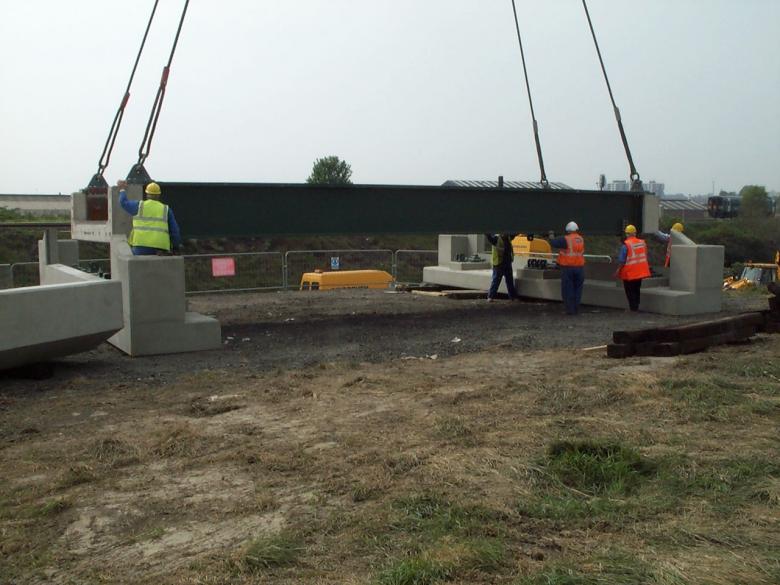
With the deck units, precast elements and crane safely on site. The trial erection of all the parts was undertaken to ensure that during the upcoming possession the replacement structure could be installed with minimal risk to possession over-run.
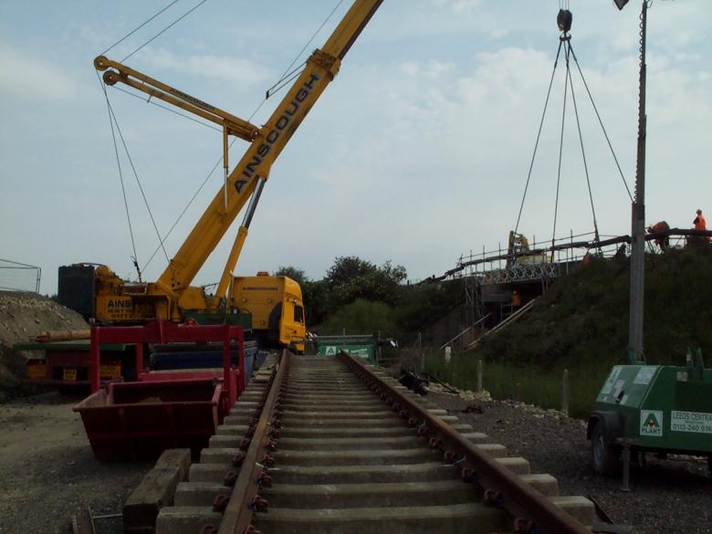
Ainscough Crane Hire Limited commence rigging the Liebherr LTM 1400 crane at 16:00 on Saturday 1st June 2002. The crane was rigged and ready for lifting at 20:00. The crane was fully rigged, out-with possession working as per the initial visit to undertake the trial lift on the 10th May 2002.
May 10th 2002 6am - crane turning into the access. Note the change in road depth - tide mark on the wall shows the change in road level.
Bridge being brough to site 50mm to spare - only just fitted.
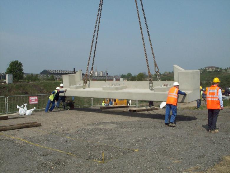
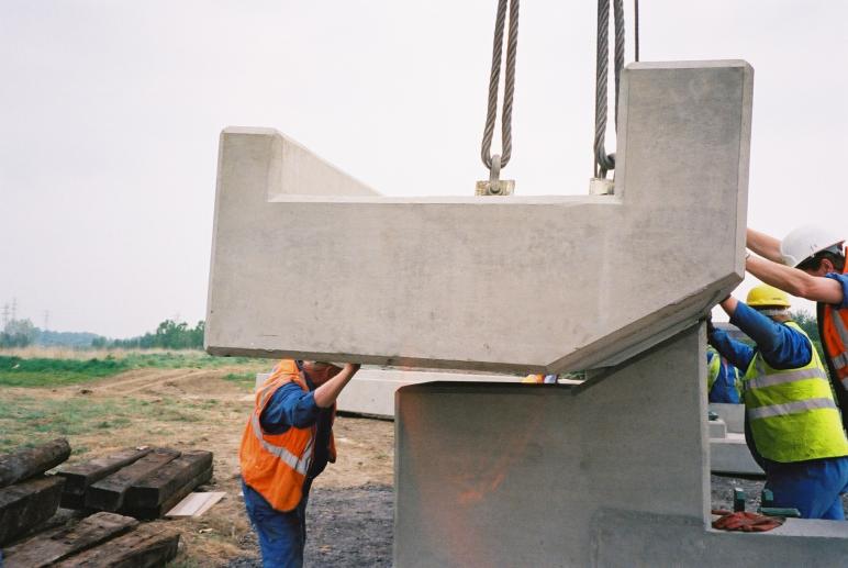
Trial erection being undertaken - David Millar looking on. Impost units supplied by Macrete Ireland.
Bridge deck being fitted out onto the concrete impost units.
Concrete edge beams being fitted out during the trial erection.
The trial erection of the structure was very successful with all the sections of the bridge fitting together nearly perfectly, however news of the trial erection went virtually unnoticed in the York main office, due to events earlier in the day. At 12:55, a West Anglia Great Northern train travelling at 97mph, bound for King's Lynn in Norfolk, (a four-car Class 365 electric multiple unit) crossed over a set of points '2182A' just south of Potters Bar railway station. As the final coach travelled over the points, they failed, causing the rear wheels of the carriage to travel onto the adjacent line and ultimately derail, flipping it into the air. The momentum carried the carriage into the station, where one end of the carriage struck a bridge parapet, sending debris onto the road below. It then mounted and slid along the platform before coming to rest under the platform canopy at 45 degrees. The front three coaches remained upright, and came to a stop to the north of the station. The derailed high speed train, killing seven and seriously injuring another eleven. Another 70 were also injured. Part of the train ended up wedged between the station platforms and building structures. The damage to the bridge was so great that it would need to be replaced and this is the subject of Project 23- ECML 149 Darkes Lane.
Stone being placed in gabion baskets ready for lifting in.
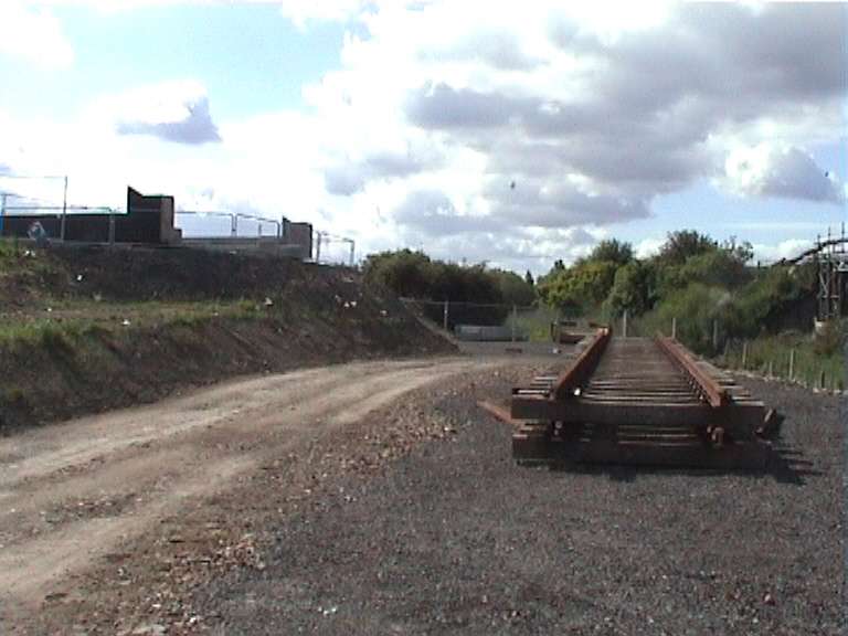
WA Development build up the track panels ready for lifting on to the bridge.
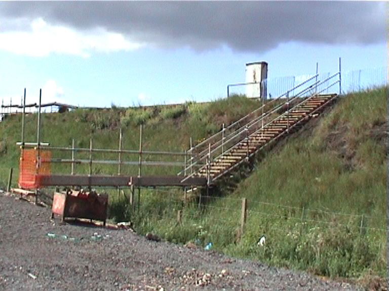
South Yorkshire Scaffold - installing an access scaffold up the embankment.
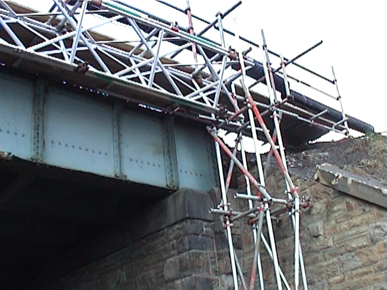
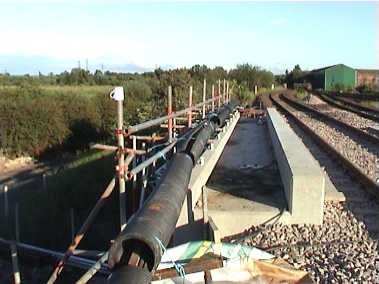
Scaffold cable bridge installed to carry the S&T - cables being lifted and shifted by ASTE.Rail.
With the access installed a scaffold cable bridge was installed to enable the cables to be moved from the cable trough on the bridge to keep them "live" during the possession. Three possession were utilised to move the cables including a possession to remove stone parapets. ASTE Rail carried out lift and shift works during the possessions, the movement of the cables was very successful, especially when originally, the works were programmed with a scheme to replace the cables over the structure and up to 600m either side (which would have made the cost of the project prohibitly expensive).
Scaffold cable bridge installed to carry cables.
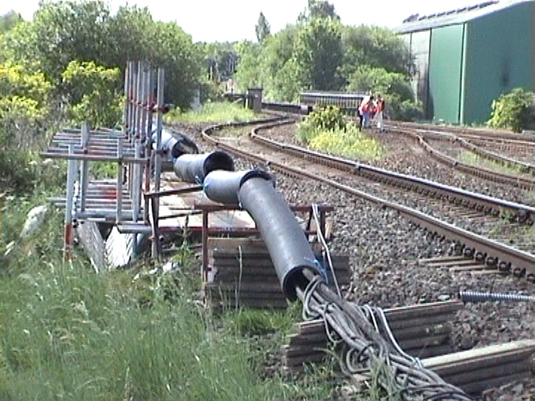
Cables lifted and shifted by ASTE rail on to the cable bridge.
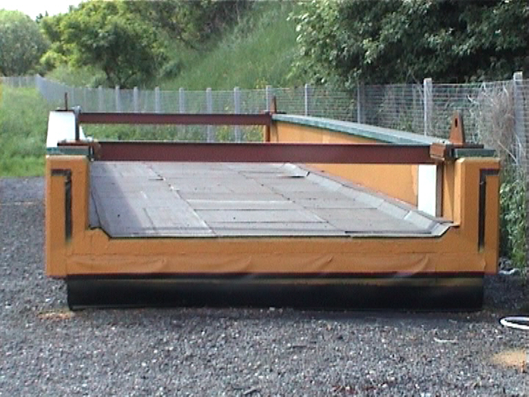
Bridge deck - set up amd waterproofed with protective boarding fitted out on the deck.
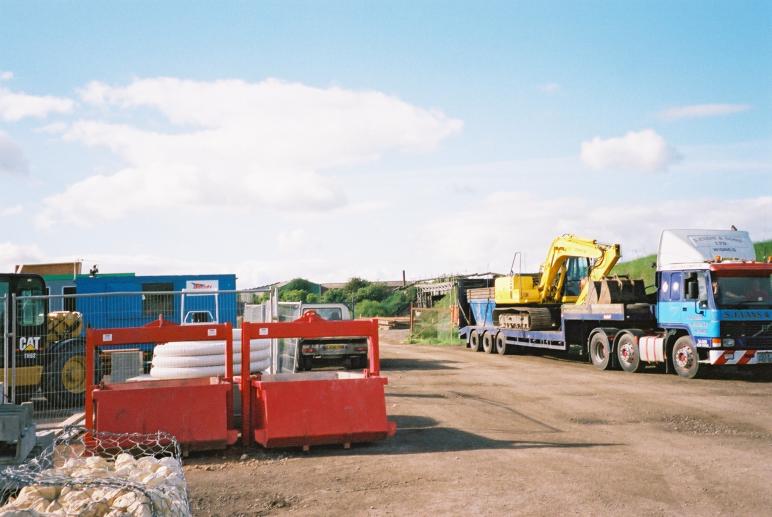
Plant and equipment being delivered to site - Sam Evans demolition plant arriving on site.
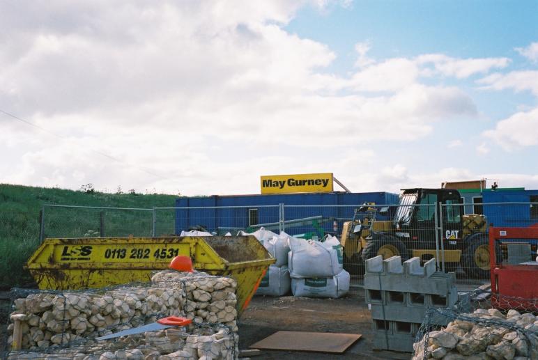
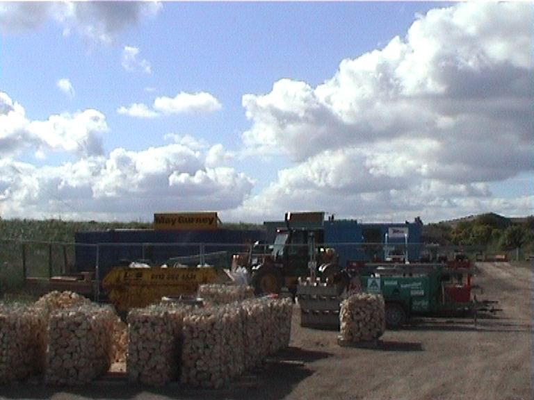
View on the May Gurney site compound - materials stockpiled ready for the possession.
53hr possession commencing at 19:30 on the 1st June 2002.
Possessions/ Protection limits and times.
Wakefield Turners Lane Jn to Calderbridge Jn (CTL)
T(iii) Possession - Up & Down Lines
Saturday 1st June 2002 @ 19:30 to Tuesday 4th June 2002 @ 00:30
Wakefield West Jn to Goole Potters Grange (WAG)
T(iii) Possession – Up & Down Lines
Saturday 1st June 2002 @ 20:40 to Sunday 2nd June 2002@ 20:00
Wakefield West Jn to Goole Potters Grange (WAG)
T(ii)H Protection (published in the WON)
Saturday 1st June 2002 @ 19:30 to Saturday 1st June 2002 @ 20:40
Sunday 2nd June 2002 @ 20:00 to Tuesday 4th June @ 00:30
Ainscough Crane Hire Limited commence rigging the Liebherr LTM 1400 crane at 16:00 on Saturday 1st June 2002. The crane was rigged and ready for lifting at 20:00. The crane was fully rigged, out-with possession working as per the initial visit to undertake the trial lift on the 10th May 2002.
The crane arrived and was driven in to position at its predetermined location, the crane was supervised through the tight WAG bridge access way by an Ainscough banksman. The work area had been extensively landscaped to enable the crane to be located in most efficient lifting position. Laydown areas were also created for the existing bridge storage and dismantling.
Staff and Operatives from S. Evans & Sons Ltd, SYS Ltd, A.S.T.E. Rail and W.A. Developments Ltd all arrived on site at 19:00 on Saturday 1st June 2002. David Millar the May Gurney site supervisor carried out a method statement briefing to all staff prior to works commencing on site, following this briefing David Millar went home handing the site over to Ian Watson. The COSS also carried out a briefing prior to commencement of the works on the track.
Preliminary Demolition Site works
At 19:30 on the 1st June 2002 the PICOP took possession of both the UP & DOWN - CTL lines. At this point the WAG lines were both still “live” to traffic. A fenced green zone was set up by the COSS in the 10 foot cess until both the UP & DOWN – WAG lines, also come under the control of the PICOP at 20:40.
At the start of the possession A.S.T.E Rail disconnect all track circuits and cables required to undertake the bridge demolition. The WAG line S&T was not affected by this disconnection work. The WAG line TPWS was taken out of commission throughout the 53hr possession. All disconnected tail cables were rolled up and placed in safe storage ready for reconnection.
On completion of the track circuit disconnection W.A. Developments cut the track at the locations either side of the bridge. May Gurney issued a Hot works permit and supplied a fire extinguisher at the work site to prevent any track level fires.
On completion of the track cuts and S&T disconnection work, the work site was handed over to the demolition contractors S. Evans & Sons Ltd at approximately 21:00.
A May Gurney supervised exclusion zone was then set up under the bridge structure to prevent unauthorised access during the demolition phase. No personnel were allowed under the bridge during the demolition operations. A physical fenced barrier was erected to prevent personnel moving into unauthorised areas. Signage was also installed as an additional warning.
Main Bridge Demolition works.
The demolition of the existing bridge span was undertaken generally inaccordance with S. Evans & Sons Ltd method statement (CTL3/MS/S.Evans 01). .
The 500t crane was utilised during the possession the by the demolition contractor to remove the redundant existing track and sleepers down to ground level for breaking up and storage.
The crane lifted up to rail level 2nr Tracked excavators on to the North and South abutments respectively (via manufacturers 4no lifting points).
The crane then lifted 2nr 8cu/yard skips on to the North and South Abutments using a proprietary lifting cradle arrangement. (via manufacturers lifting points)
The excavators were used to dig out the existing ballast from the bridge deck and also 4m either side of the abutment. The ballast was loaded into the skips. Once full, the skips were lifted by crane and tipped into a visqueen lined storage area at road level.
Excavators were used to dig out the loose fill from behind each abutment down to bearing shelf level and along the line of the main cut. On completion of the excavation both excavators retired to a safe possession back from the bridge abutments.
The lead content of the paint on the existing structure was analysed at 0.1%. Suitable breathing apparatus was required to be worn by operatives whilst cutting up the existing girders. Also a decontamination unit was provided in the May Gurney Compound.
Four number operatives used oxy/propane cutting equipment to cut lifting holes through the existing bridge buckle plate. The 300 square holes were cut in the bridge deck at 2/3rd Centres adjacent to each lifting point. Operatives broke away the protective asphalt waterproofing from the deck plate adjacent to No 3 Main Girder.
Collar chains are to be passed through holes in the bridge deck and around the main girders (chains were attached using ropes) and secured to the cranes lifting tackle thus performing a six-point lift.
Tag lines were fixed to the main bridge deck to be lifted out.
The two 13t excavators were utilised to prevent the bridge deck moving laterally toward the temporary Scaffold Cable Bridge during the bridge removal. The excavators extend their booms and place their buckets against the inside main girder. During the controlled lift the excavators removed their buckets once the bridge deck is clear of the cable bridge. (the existing structure was been lifted 1.2m above its initial start position).
The crane lifted the existing structure clear of the existing abutment and place it in a predetermined laydown handling area next to the crane. Initially the crane took the strain up to 40t, where the lift was halted to check for abutment fixings. To free up the bridge main girders, the crane lifted each corner of the structure applying enough force to free the girder from the bearing shelf, this technique prevents enough force being applied to pull the structure of the abutment.
The two excavators situated on either abutment were used to break out and remove the existing bearing stones down to the proposed new underside of cill beam level.
Debris was loaded into waiting skips for lifting out and removal by crane.
Edge protection was installed to the existing abutments using a series of tower scaffolds linked together and anchored with ringbolts to the abutment face. These could only be fully installed following the completion of the removal of the bed stones.
Phase 1 Demolition down to the formation level for the new cill beams was programmed for completion at 08:00 on the 2nd June 2002 ready for hand over to the next May Gurney supervisor (David Millar), however work progressed on the structure removal such that the work was completed by 04.00 some 4hrs ahead of programme.
South Yorkshire Scaffold operatives completed the erection of a series of tower scaffolds linked together in front of each abutment to provide edge protection and safe access to install the new pre-cast concrete cill beams.
With the edge protection installed May Operatives were able to lay the mortar bed seating for the pre-cast cill beam units. The levels for the units were fixed using a series of shims and timber screed rails. Operatives mixed 3/1 Sand cement mortar at the back of the abutments with the mortar mix screeded of to level and lightly tamped with a compacting plate.
The pre-cast cill beam units were lifted into position using the 500t crane and proprietary star-con 20t lift heads. A May Gurney Engineer levelled and align each of the bridge cill units to enable each of the bridge units to be connected together.
Bridge removed with impost unit lifted in and positioned.
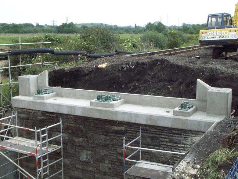
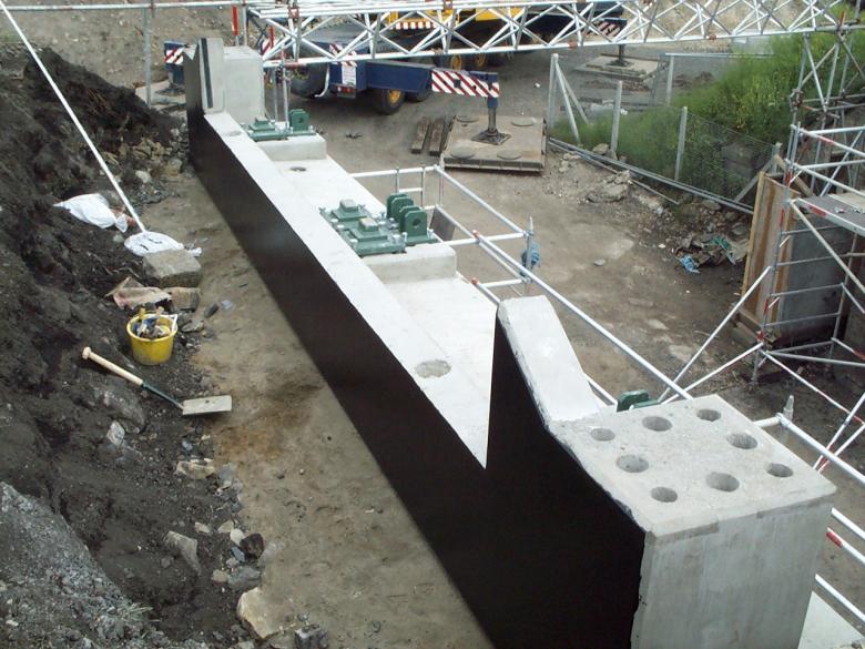
Impost unit set up on the abutment. Note the bearings set up ready for the deck.
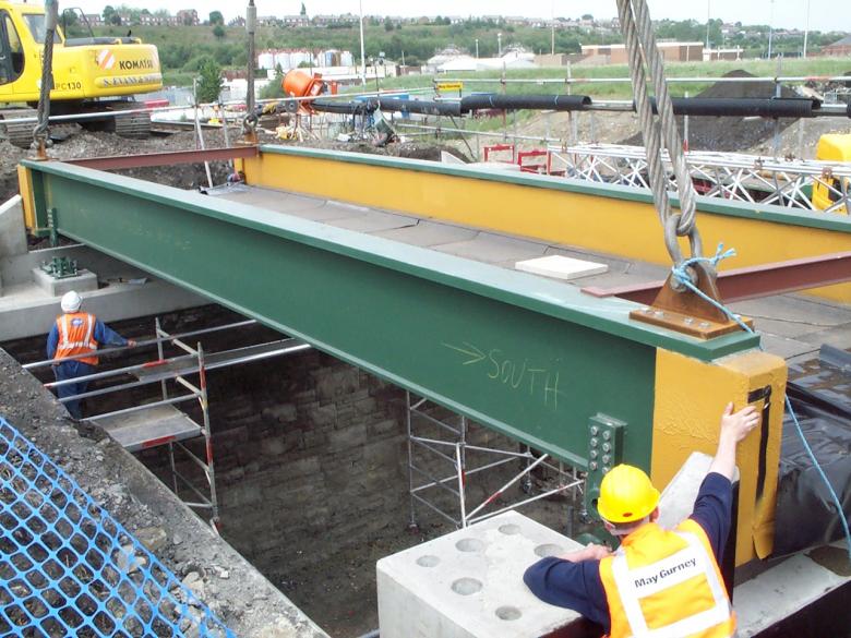
Bridge Deck being lifted into place - David Millar on the corner.
2nd bridge deck being installed - David Millar on the deck.
Bridge Walkway units being lifted in and connected up.
On completion of erection of the main bridge “U” decks the Sub-contractor Waterseal (waterbar and sealants) Ltd undertook the work to heat weld the Wolfin membrane to the AF6 pre-cast strips on the deck ends and cill beam upstands. The wolfin membrane was draped into the pit beneath the carrier drain. The membrane was protected with 1000gm Geotextile loose laid.
May Gurney operatives installed concrete slabs to the deck ends and at the returns joining the bridge decks together. May Gurney Operatives also to install the 150mm dia Perforated pipe fully surrounded with 150mm pea gravel.
The back of the abutment was backfilled with clean bottom ballast lifted into position by crane and skip (8cu/yard skip to be lifted using a proprietary lifting cradle arrangement). The ballast was spread by a 360 excavator at track level and compacted by Bomag 1200mm Roller (lifted on to track by crane).
With the back of the abutments back- filled the walkway units were lifted into position and landed into the required location. The temporary cable bridge was designed to enable the new walkway unit to fit into position, however great care was taken lifting next to such a sensitive structure.
The 500t crane was utilised to lift and place ballast up to the underside of track sleeper level. A series of stone filled gabion baskets (12nr) were also lifted into position. The gabions are provided to retain the ballast and stop it falling through to the roadway below.
Following completion of the ballast installation the crane lifted the tracked excavators and roller from track level to the ground utilising the manufacturers 4no lifting points.
With the track ballast installed and compacted up to the underside of sleeper level May Gurney are to hand over the track bed area of site to W.A. Developments to start re-installation of the P-Way. A series of track panels were pre-assembled prior to the possession ready for installation during the possession. The 500t crane lift the track panels into position using a spreader beam.
Concrete edge beams installed to the bridge - cables in place on the temporary bridge.
One end of the rails was fixed with stepped fishplates and the other end cut to the correct length. The cut rail were drilled and CBXed the rails were then fitted with new stepped fish plates. The new top ballast was loaded into the colmar trailer, taken to site and placed in the required bays. The track was then lifted to line and level and then tamped with the RRV and tamping bank.
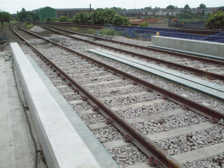
Bridge with new track running over the bridge. Note tight alignment with the girders and sleepers.
Post possession - cable bridge carrying cables.
On completion of the P-Way installation the track was certified by W.A. Developments as being fit to return to operational traffic. ASTE Rail reconnected all track circuits and S&T cables and caried out all testing required to certify the S&T as fit to return to operational traffic. A May Gurney supervisor David Millar inspected the work site and undertake any snagging required to open the new bridge structure to operational traffic. On completion of the snagging and site clearance works, the May Gurney supervisor provide the PICOP with clearance to open the P-way to operational traffic via the COSS and Engineering Supervisor.
Gabion baskets installed to retain ballast between the new deck and the existing WAG structure.
Gabion baskets sat on the girders to retain the ballast.
New concrete deck installed to carry cables and provide a new walkway.
Cables running across the cable bridge.
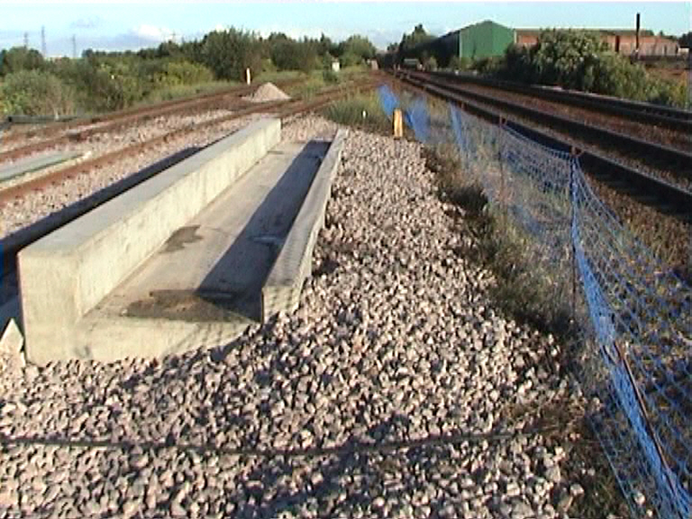
Internal precast concrete walkway installed.
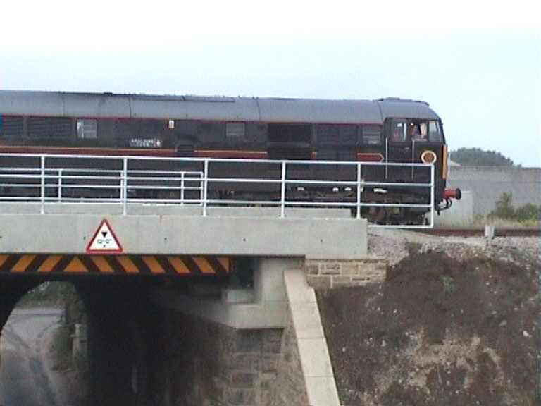
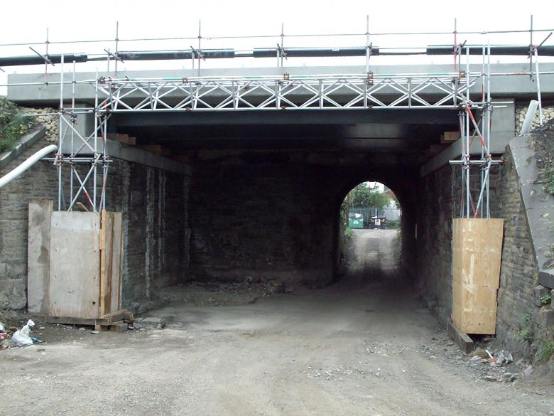
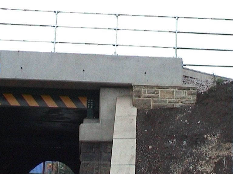
Locomative running overthe new structure - with stone walling completed and height barriers installed.
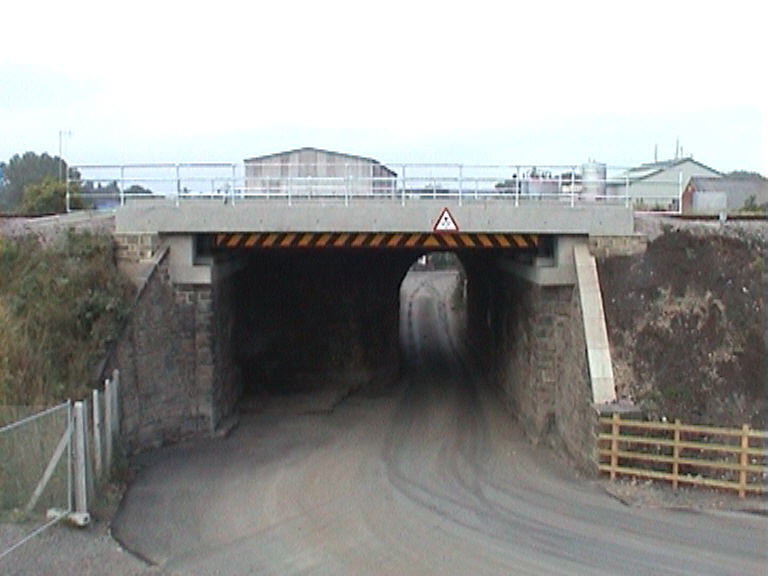
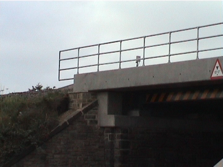
View on the completed structure with stone walls completed and fences installed.
Stone Wingwall completed - concrete imposts pointed up.
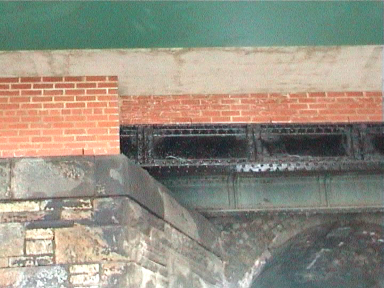
Brickwork installed on the edge girders - girders painted black.
Edge beams - stone work set up on the wingwalls.
Stonework set up on the wingwalls - Kee clamp handrails completed.
Page under construction...
| 