|
Bridge replacement - Demolition of the existing road bridge and replacement with a New Footbridge. This is the first full project undertaken by David Millar with Terry Loney as General Foreman.
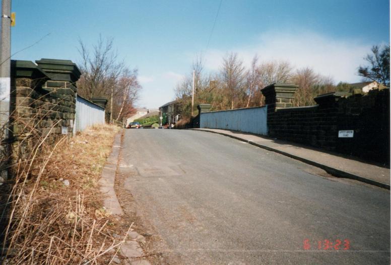
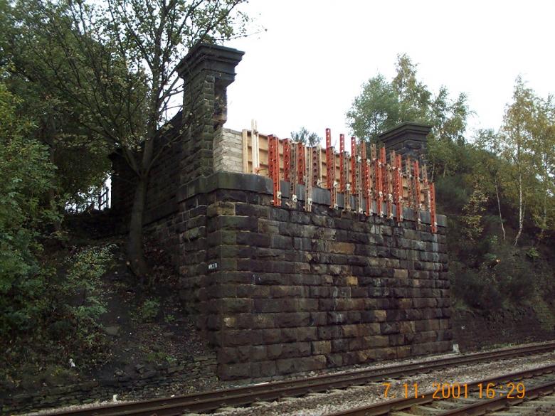
View on the existing bridge stucture
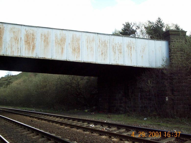
View on the existing structure looking from track level - Note depth of the Box girder.
The scope of this project was to demolish and replace the existing late Victorian road bridge with a new footbridge. The site was located at Upper Brow Road /Clough Lane in the Paddock district of Huddersfield, West Yorkshire. I first looked at this project while at Nineveh Road in Leeds during August 2001. I set up a number of contracts with sub-contractors while the main office arranged the procurement of the main structural elements in the shape of the new steel footbridge from Carver Steel Fabrication and precast concrete impost units from Ewans concrete products Ltd. While in Leeds I set up the procurement of the demolition contractors MGL (Demolition) ltd and put together the most acceptable tender for the works based on safety, quality and cost. Work on the site started during the first week in September with Terry Loney clearing an area at the side of the existing bridge to enable the site cabins to be located the 17th September 01.
The project was designed by Corus Rail Consultancy who provided drawings covering the main footbridge and turning heads either side of the bridge. Work on site started as soon as the cabins had been set up with the removal of the trees and bushes in the turning head areas.
The Initial demolition works was carried out by MGL (Demolition) Ltd, from week commencing 24th September 2001 for approximately three weeks - in three 10hr rules possessions. Protection of the railway infrastructure was via a series of pre-programmed T(iii) possessions of the MVL3 main lines. Possession Management was provided by Bridgeway Consulting Ltd.
Possession No 1 (30th September 2001 –00:20 to 09:00)
A light duty crash deck was installed at the start of the possession to protect the track from any falling debris this will took the form of timber sleepers with a ply wood covering. A May Gurney supervised exclusion zone was set up under the beams to prevent unauthorised access during the demolition phase. No personnel were allowed under the bridge during the main lifting operation. Prior to excavation starting a permit to dig was be issued by May Gurney all services had been previously disconnected prior to the site being set up on site. During the possession two 3600 Excavators were located at road level behind the abutments breaking up the surfacing and feeding debris on to a stock pile of material ready for removal off-site during normal working hours. The deck plates were full exposed to enable cutting in the next possession. The crash deck was cleaned of all debris (as expected due to buckle plate construction, condition and method of excavation) no debris had fallen. Prior to hand back of the possession the crash deck was fully removed and stored ready for future reuse in the area in front of the South Abutment. The track and bridge were inspected by David Millar prior to hand-back.
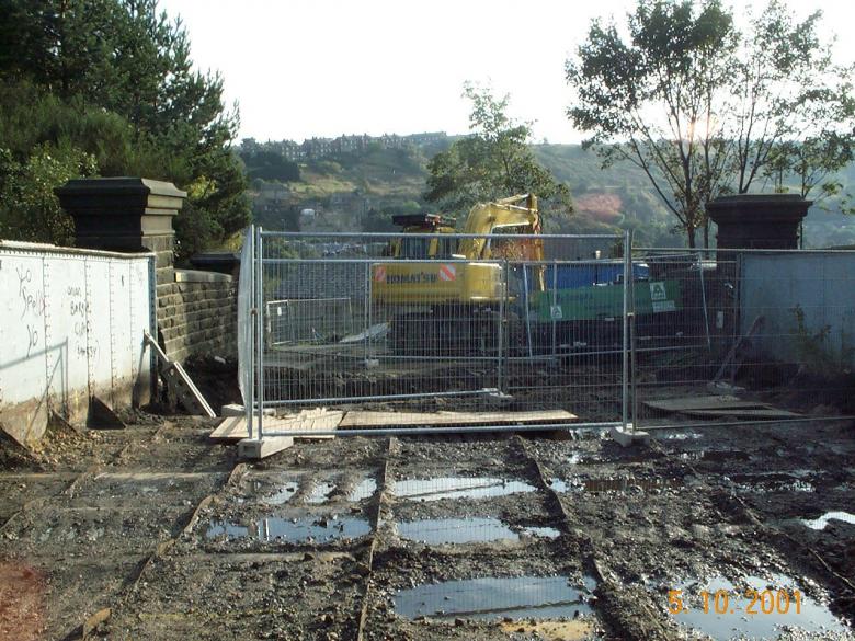
Bridge deck surfacing removed during possession by MGL Demolition.
Possession No 2 (6th October 2001 –23:00 to 7th October 2001 -09:00)
A light duty crash deck was installed at the start of the possession to protect the track from any falling debris this took the form of timber sleepers with a ply wood covering. A May Gurney supervised exclusion zone was set up under the beams to prevent unauthorised access during the demolition phase. No personnel were allowed under the bridge during the main lifting operation. A Fire extinguisher was located with firewatcher at track level to prevent any fires on track. The buckle plates were cut centrally across the width of the bridge to enable removal with the cross girders. Hot works permit and fire extinguisher were located close to the working area. Access to cut the buckle plates and girders was from above standing on the buckle plates and cross girders and below via a scaffold tower founded on the track bed. Operatives working at height are required to wear safety harnesses and be fully secured at all times.
The Crane operation diagram: Crane assembly and demobilisation position and Crane working Radius.
Prior to loading of crane outriggers the stability and load bearing capacity of the ground under each spreader mat was assessed by a competent person (David Millar). The close proximity of utilities at loading positions was taken into account during this assessment. Radio detection used to locate services.
Possession 2 - Demolition of the main structural steelwork involved the removal of the following:- 9 nr 9.2m long internal cross girders (approx. 1.6t each & 6 nr (varying lengths) internal trimmer beams (approx. 0.4t – 0.7t each) During this possession six number trimmer girders (T1-T6) and Nine number internal girders No 1,2,3,5,6,7,9,10,11 were removed. Leaving the two main box edge girders (M1 & M2) and three internal cross girders along with the temporary works fixed to these three girders.
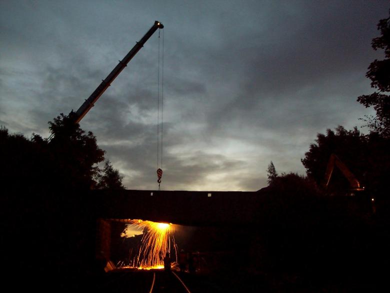
Once the chains were located and balanced the girders were cut (with flame burners oxy-propane) and lifted free. The girders were controlled by attached hand lines and directed to a suitable predetermined laydown area (to the rear of the crane in the site compound) for cutting up and loading away.
All girders removed were taken off site prior to the end of the possession. This ensured that no access roads in to the site are blocked to the general public and also to enable the crane to be de-rigged.
The lead content of the paint on the existing structure was analysed at 28%, before cutting operations were undertaken suitable breathing apparatus were worn by operatives cutting up the existing girders.
At the end of the possession the crash deck was cleaned of all debris with all rubble present was stock piled (in a fenced area) in the wide cess near the south abutment. Prior to hand back of the possession the crash deck was fully removed and stored ready for future reuse.
The track and remaining bridge were inspected by May Gurney site supervisor (David Millar) and Engineering Supervisor prior to hand back.
At the start of the possession - while trying to find the crane which had got lost (on its way in from the M62) David Millar found out on the radio that Railtrack were being put into administration - What to do ? stop the works ? or keep going and sort out the comercial side with the demolition contractor once the work were done. In the end it was a case that the show must go on.
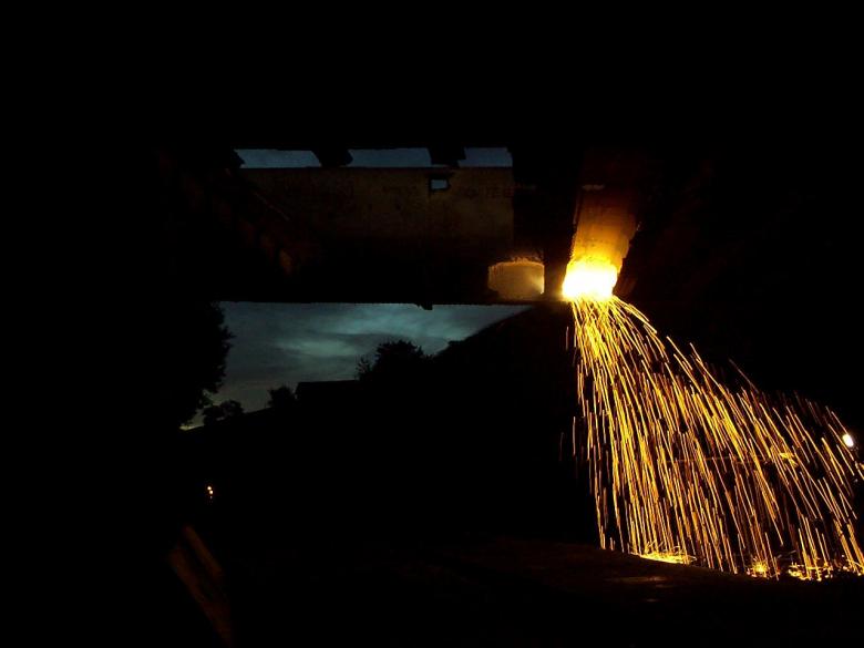
MGL Demolition in progress - cutting the deck buckle plates.
Crane lifting out the buckle plates out as they are cut free - full crash deck installed to protect the track bed.
Lifting holes cut in the box girders ready for lifting.
Possession No 3 (13th October 2001 –23:10 to 14th October 2001-09:00)
No crash deck was installed for this possession as lifts are steelwork only. All rubble/excavated material was removed during the previous two possessions.May Gurney supervised exclusion zone was set up under the beams to prevent unauthorised access during the demolition phase. No personnel were allowed under the bridge during the main lifting operation. A Fire extinguisher was located with firewatcher at track level to prevent any fires on track during the cutting phase for lifting points.
Prior to loading of crane outriggers the stability and load bearing capacity of the ground under each spreader mat were assessed by a competent person (Appointed person Lift Co-ordinator). The close proximity of utilities at loading positions was taken into account during this assessment. Prior to any lifting operation the wind speed shall be monitored to ensure any lifts are to be undertaken at below the safe working limit for the crane.
Demolition of the main structural steelwork involved the removal of the following:- 2nr 17.4m long box edge girders (approx. 13t each) 3nr 9.2m long internal cross girders (approx. 1.6t each)
During this possession it the remaining three internal girders No 4,8 & 12 along with the temporary works support were removed along with the two main box edge girders.
Operatives working at height were required to wear safety harnesses and be fully secured at all times. Once the chains are located and balanced the girders were cut (with flame burners) and lifted free. The girders were controlled by attached hand lines and directed to a suitable predetermined laydown area (to the rear of the crane in the site compound) for cutting up and loading away.
All girders removed will be taken off site prior to the end of the possession. This is to ensure that no access roads in to the site are blocked to the general public and also to enable the crane to be de-rigged At the end of the possession the track was inspected by May Gurney site supervisor (David Millar) and Engineering Supervisor prior to hand back.
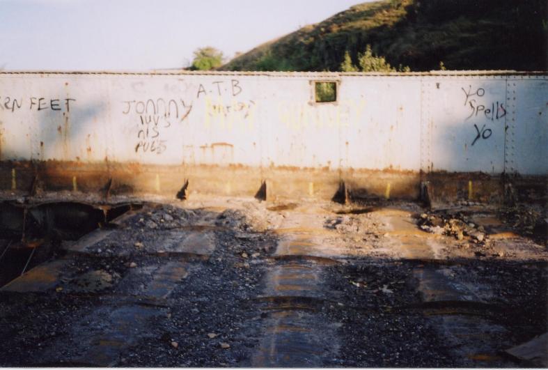
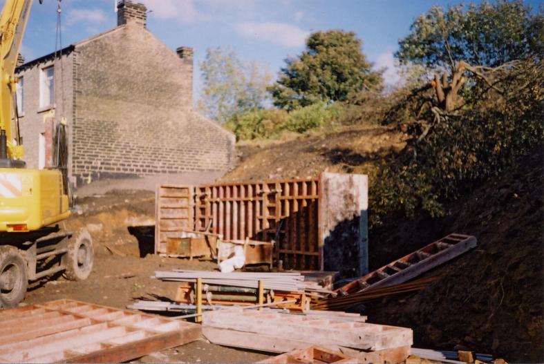
Bridge Girders removed fully during an 8hr possession. View on the abutment.
View on the abutment - scaffold erected infront of the abutment - crash deck materials stockpiled infront of the abutment.
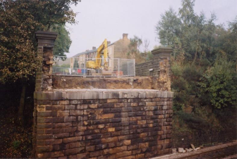
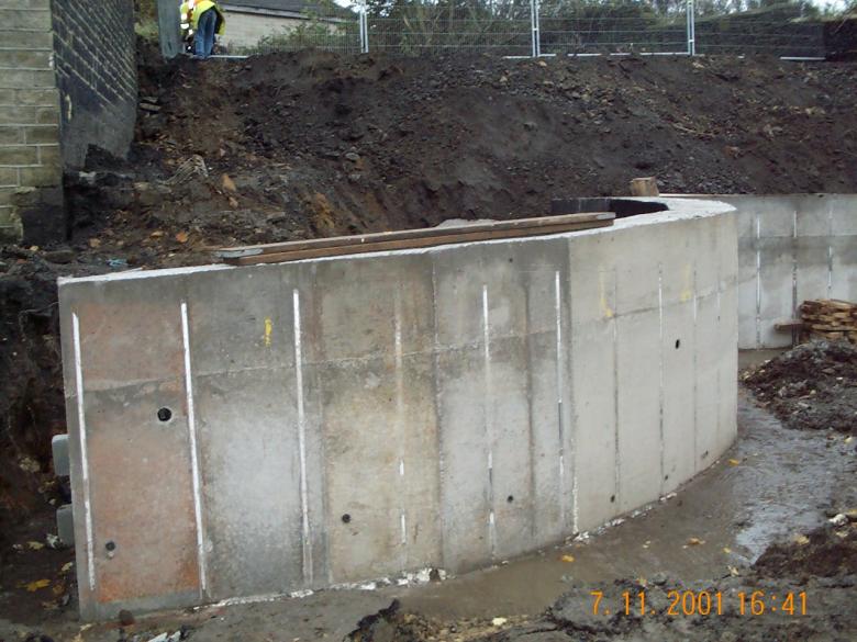
During October 2001 - works progressed with building mass concrete foundations on top of the existing abutments ready for the installation of the concrete impost units. Formwork for the mass concrete pour was designed by David Millar - with the RMD's being fixed with epoxy fixings into the face of the abutment. The corner returns of at the end of the formwork were built from heavy duty concrete blocks ready for mass fill concrete.
Formwork - set up on the abutment - Note the RMD's set up and fixed into the abutment face with Hilti-Hy 500 + dywidag anchorages.
North abutment - formwork being erected for concrete.
During normal working work progressed on both the North and south turning heads. The North turning head being created from RMD trapizod shutter system lined with thin hard board to create a smooth curved wall. A 360 Degree rubber tyre excavator being retained on site to do all lifting digging and material movement - this machine was used as it was able to travel around to both sides of the work area (a distance of about 2miles now that traffic was stopped going over the bridge).
RMD curved concrete retaining walls.
The precast concrete -impost units for the new bridge were installed during a 10hr possession on the 10th/11th Nov 2001. An 80t crane supplied by Baldwins Ltd was used to lift into place the 5t side units and 2.5t bridge impost units. David Millar set the location and level of the units with the assistance of Mark Bannister. Once in place the units were fixed in place using long holding down bolts drilled into the mass concrete and fixed with cementitious mortar. Once in place the elastomeric bearings were fixed and set ready installation of the main bridge structure.
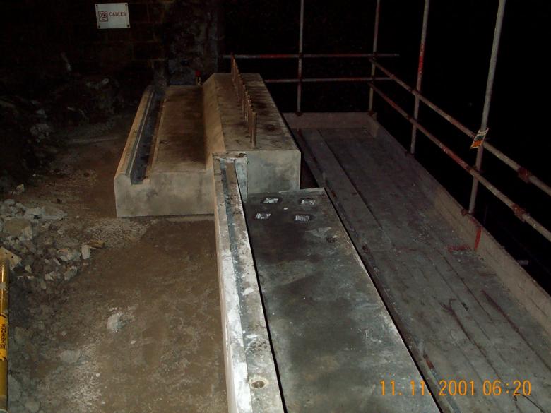
Pre-cast concrete impost units drilled and set up on the abutments.
During Possession No7/No8 on the10th & 18th November 2001 the pre-cast concrete impost foundation units (6nr) and elastomeric bearings were installed by May Gurney prior to delivery of the bridge to site. The new Bridle-way bridge was prefabricated (as per contract drawings 50022-001 to 012) and delivered to site by Carver Engineering Ltd for erection in a 10hr possession commencing on Saturday 17th November 2001 at 23:00 and ending on Sunday 18th November 2001 at 09:00 (as per contract drawings 50022-001 to 012).
The new structure was fabricated by Carver Steel near Doncaster - before it was shipped to Jack Tighe for painting (also in Doncaster). The structure it self is approx 3m wide 18m long with 2m high parapets - weight of nearly 15.5t. Baldwin Crane hire supplied the crane for the lifting operations - 180t Grove GMK 5180 located on the North side of the proposed structure.
Prior to loading of crane outriggers the stability and load bearing capacity of the ground under each spreader mat was assessed by a competent person (lift co-ordiantor). During the demolition phase a 200t Grove crane easily lifted 18.5t sitting on the same foundation positions. The crane was rigged immediately prior to the possession (as per demolition phase). The crane was driven into position at the back of the North abutment (proximity limit set by timber sleepers), under the supervision of a banksman (minimum 4m from abutment face to outrigger centre), the ballast lorry was park up in front of the crane. The bridge was delivered to site on an unassisted road going vehicle conforming to the various HGV Categories of the Road traffic act. The lorry was reversed up to the crane ready for lifting. Short Ladders were used to enable rigger operatives to access and place chains/slings on the sections to be lifted. Operatives working at height were required to wear safety harnesses (hooked onto the crane block) and be fully secured at all times (it was not expected that any operatives will require to work at any height above 1.5m).
All chains and lifting gear used during the course of the main lifting operations, were marked with their safe working load “SWL”.
Once the slings are attached and balanced the crane lifted the bridge clear of the transport lorry and slew through 180 degrees. The bridge was lifted in a manner, which enables both ends of the bridge to be landed simultaneously on the impost units. The southern side of the bridge was set 1.48m lower than the northern side. Lifting lines attached to the bridge enabled the lift to be controlled and landed in the correct position. Once landed the bridge was braced with timbers and bolted up prior to removing the lifting tackle. The bridge was aligned and levelled by a May Gurney Engineer prior to the grouting up the bearings following completion of the possession during normal working.
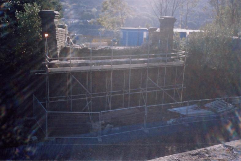
During the course of subsequent possessions it was possible for May Gurney Operatives to continue the construction of the masonry walls and parapets. Edge protection to the North abutment will be provided by a series of tower scaffolds as per the last three possessions during the installation of the impost units, South Yorkshire Scaffold provided operatives to assist in erection of the scaffold and to ensure the scaffolds stability during the course of the masonry installation.
New bridge installed during a 8hr possession - stone work being built up on the abutment.
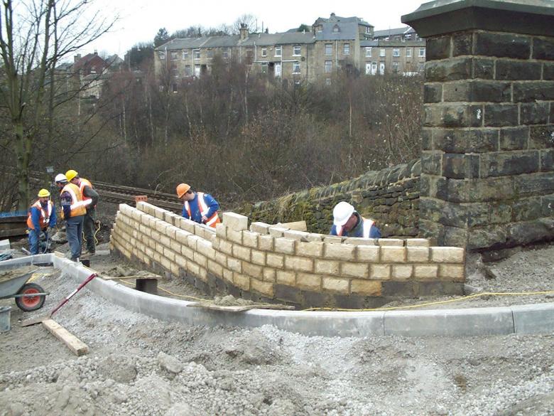
Southern - turning head - stone walls being built by Andy Skyes.

North Turning head installed - with high quality capping stones being installed - kerbs being set up.
The works to complete the stone P6 parapets on the abutments carried on until the end of December 2001,with the work on the South abutment being undertaken during normal day time working along with the southern turning head. The northern turning head was also undertaken during normal working, while the parapet on the North abutment completed during a series of short duration possessions (8 hrs) on Saturday Nights up to the end of Dec 2001. The project was finally completed at the end of January 2002 with the site being handed over to Network Rail(structure) and Kirkless District council(road and footpaths). With the project completed David Millar moved back to the York office to work on the programme and planning of thenext project CTL3 Wakefield -Waterworks Tip (see Project11).
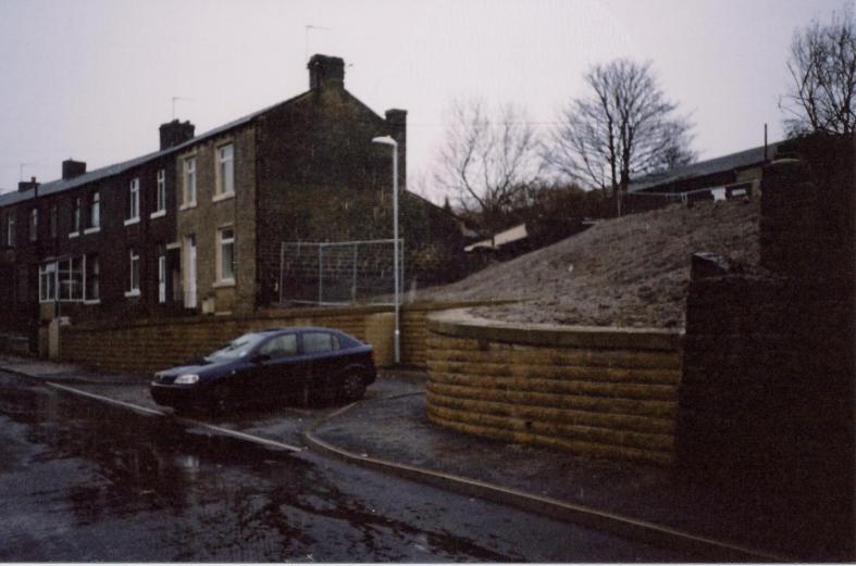
Completed turning head - backfilled and topsoiled.
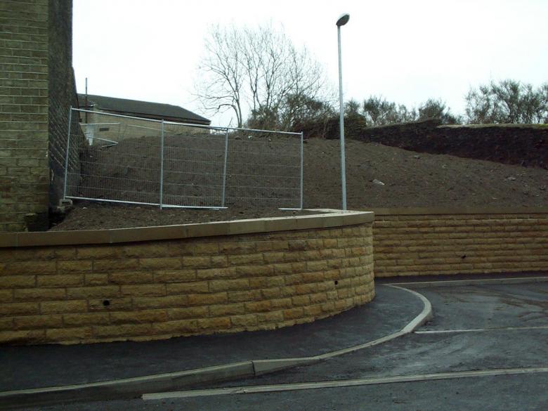
North turning head set up - note the high quality top stone.
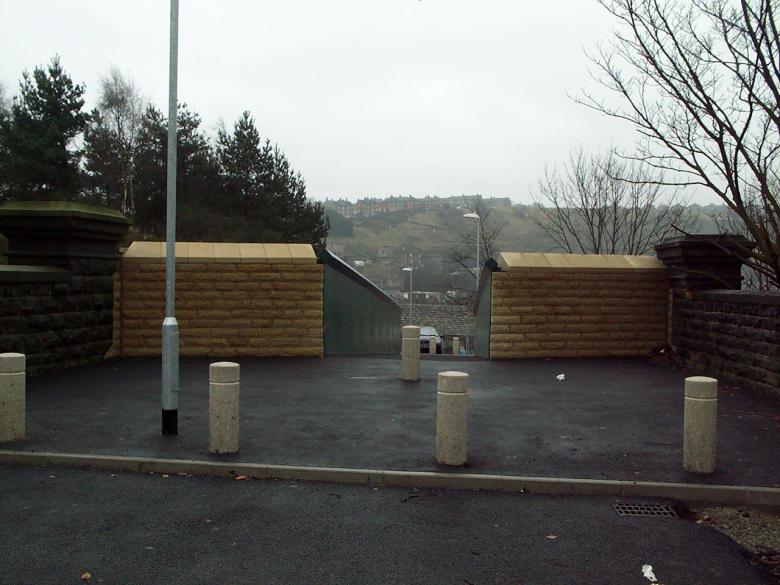
View on the North abutment approach to the bridge - bollards in place to stop cars passing over the bridge.
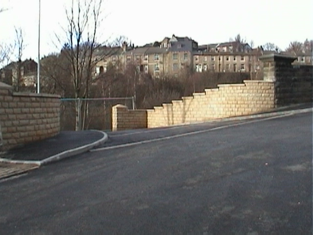
Southern turning head stone wall completed.
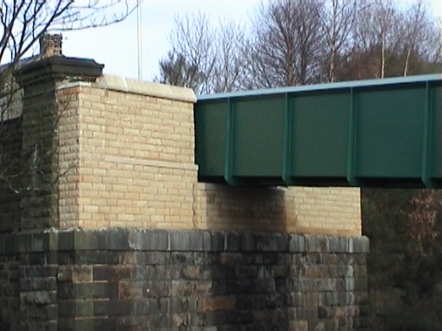
View on the North abutment stone work. This stone work was constructed during possession from scaffold tower.
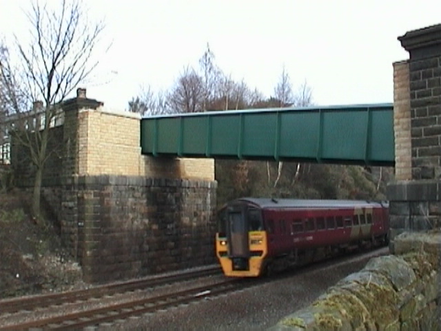
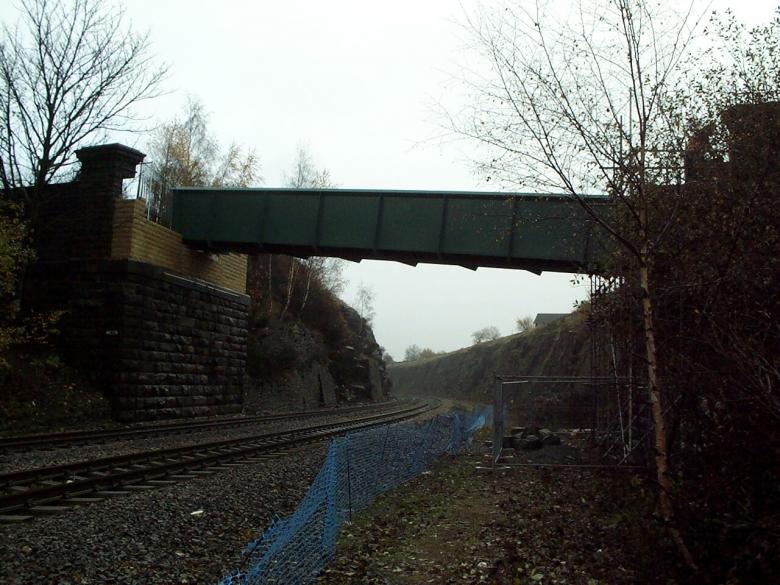
View on the completed bridge - Manchester Airport Train running under the bridge.
Paul David (Construction Manager)
David Millar ( Site- Agent )
Rob Proctor (Works Manager )
Terry Loney ( General Foreman )
Mark Bannister (Sub Agent) Andy Sykes – Stone Manson & Labour
| 