|
Railway Bridge Replacement in Leeds - This project is a good example of where the programme was developed (by Ian Watson) to enable the utilities(in this case a high pressure gas main) to remain " live" for the duration of the project. This project also provided an example of lateral thinking with regard to the demolition of the side spans. With limited track possessions available to remove the entire three span structure the design and site team looked at the demolition of the side spans first to enable the abutments to be constructed. This project was also the First project for David Millar with May Gurney after moving from Halcrow in May 2001.

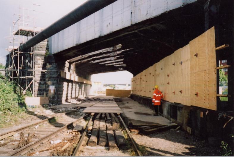
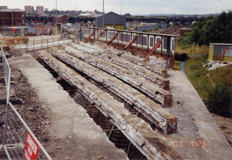
Existing structure view along the siding into holbeck.
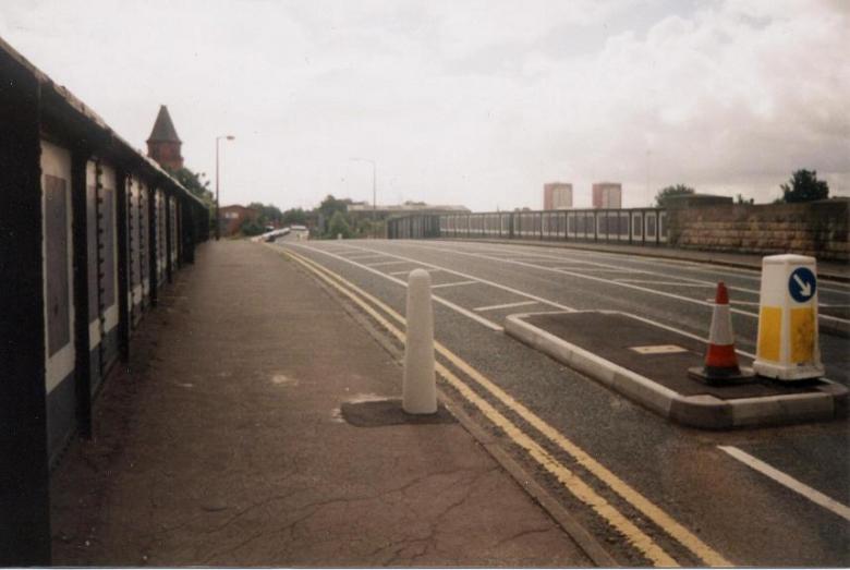
View on the existing structure just before the bridge was closed for reconstruction.
TJC3 Bridge 17 - Nineveh road bridge - was constructed in the 1890's - the three span structure has been of limited strategic importance to the Leeds transport network mainly due to a 3t weight restriction imposed in the late 1980's. The need to replace the structure to improve the transport links in the Holbeck area was identified by Leeds City Council, who put pressure on to Railtrack to undertake strengthening works to the structure - following a series of feasibilty studies - Mott Macdonald were tasked with designing a new structure to replace the existing. The design of the structure was further complicated by the need to keep "live" or divert a high pressure gas main and several fibre-optic cables running over the structure (the gas main was actually attached to the side of the structure). Further complications were added by Railtrack themselves who required the structure to be a single span structure (creating a bridge span of 50m) and to have a minimum track clearance to enable future over head lines to be installed (creating an issue with the need to alter the approach ramps and road alignment).
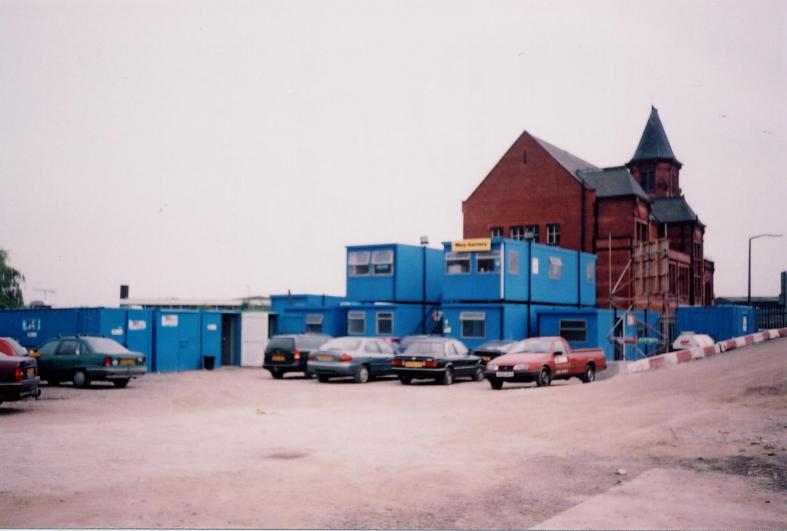
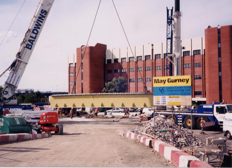
Site compound set up in the yard - really good site set up shared with Cairncross Civil Engineering.
The project office was located in the overflow carpark of the nearby mail order warehouse with an access being formed from nineveh road down into the site compound.
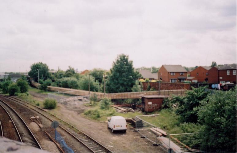
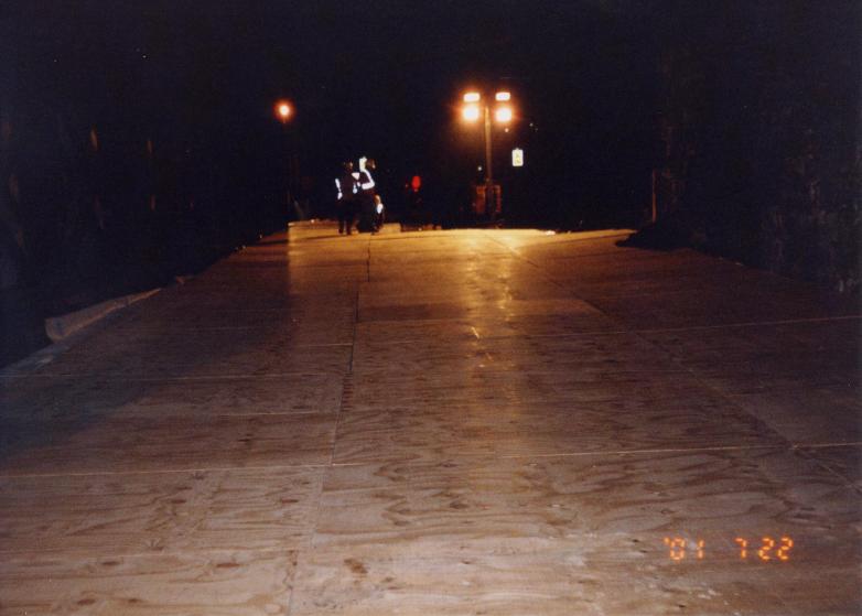
Prior to the bridge being closed a temporary walkway was erected away from Nineveh road up to the existing footbridge further up the track.
During April 2001 - May Gurney installed a temporary footway created in scaffold with timber anti-slip walking route down to a nearby Footbridge.
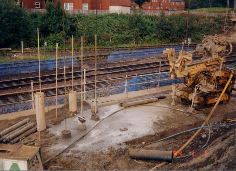
The site was set up in March 2001 by which time the main road over the bridge was reduced down to a signal lane under traffic light control. With the traffic mangement in place work was able to commence on mini piling to the abutments. The piles in the abutment were drilled from road level using a down the hole hammer - compressed air forced down the drill hole to force out the loose rock and material. Each pile was drilled and cased with a steel casing a central 40mm dia steel reinforcement bar set in the centre of the casing once completed the pile was grouted using cement. A number of the piles were drilled at an angle to provide increased horizontal load bearing. The pile placement took a number of weeks to complete - the main issue with the piles being a series of water lenses that appear throught the strat - the compressed air forced the water to the road level and out at high pressure causing the water to blow out of the casing showering the operatives with muddy water. Controls were put in place at the top of the pile case to prevent this occurance- this control measure actually took the form of an off cut of carpet located over the pile case (a simple but effective solution).
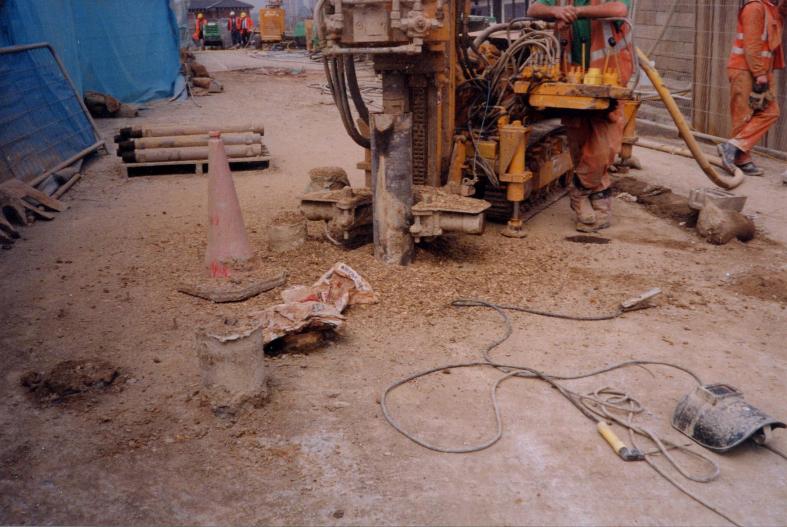
Mini piling rig set up on the deck drilling and welding steel casings.
West end of the existing bridge - brick arches being broken through - T(iv) possession
The West side span was located above the Engine Shed Junction Sidings which required a T(iv) possession of the line into the engineering yard is managed by Jarvis Facilities, who have been made fully aware of the works being undertaken. Upon taking possession of the sidings a diamond saw guide track was installed at approximately 2.5m –3m above ground level running horizontal along the length each abutment (East Abutment access was available without possession). Access to install the track and diamond bladed wall saw was undertaken off mobile access scaffold towers. The track was broken down into 1.5m lengths, which were bolted together and held on the wall with series of drilled and fixed anchor bolts. Once operational the track saw was operated from a remote location following connection to a suitable temporary water and power supply. In the event of a tamper requiring to either enter or exit Engine Shed Junction the T(iv) possession was given up and the re-taken as required.
West end of the existing bridge - brick arches being broken through - T(iv) possession
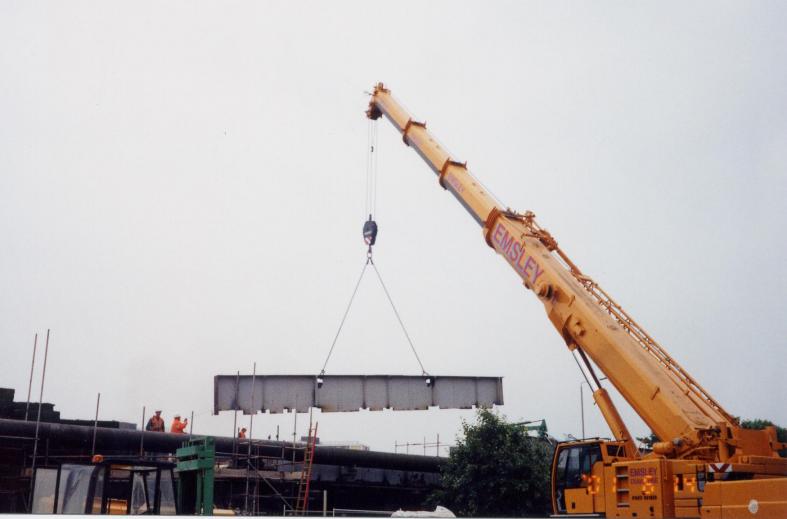
From the 3rd June 01, Barron Demolition carried out works to remove the redundant gas main pipework on the north face of the existing bridge. With the gas main removed the demolition of the west side span was undertaken, this involved the removal of 9nr 7tonne cross girders and 2nr 12t main edge girders. The two edge girders were cut horizontally in half with flame cutting equipment and lifted out in two sections (thus the lift load will be reduced to below 7 tonnes) the southern outside girders could not be removed due to the "live" gas main located on the outside of the southern bridge girder. The West side span construction was made up of girders connected by brick jack arches, the girders themselves were held together by tie bars. All girder loads were checked by the demolition contractor prior to lifting, following removal of jack arches and road surfacing.
Girders being exposed - brickwork broken out in the beam ready to cut the beam free.
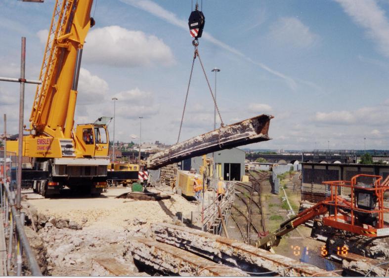
100t crane lifting out the bridge girders as they are cut free by MGL Demolition - T(iv)
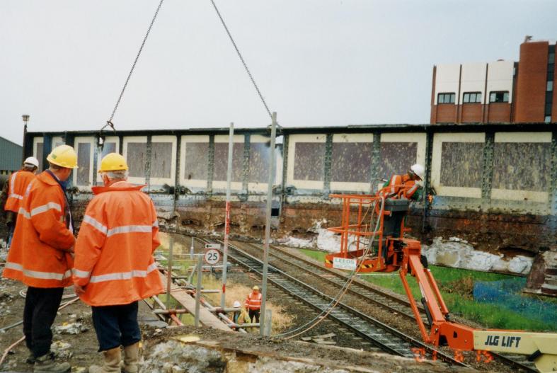
Edge girder being cut free set up on the crane note the holes cut in the web of the girder. Ian Watson and Andy Finerty Look on.
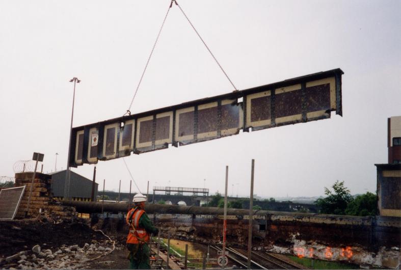
Girder cut free and lifted out - leaving the lower section for lifting out after the redundant gas main is cut free.
Section of redundant gas main cut up and lifted out.
Bottom section of the girder lifted free and out - Ian Watson and David Millar + Andy Finerty looking on.
West end of the existing bridge - works progressing during normal working to remove the girders.
The East side span of the structure was demolished following removal of the West span. The East span was made up of girders and buckle plates with a mix of concrete and granular fill on bitumen based waterproofing. This side span was demolished using a 34t excavator sat on the abutment with he buckle plates being cut free and lifted out along with the internal buckle plates.
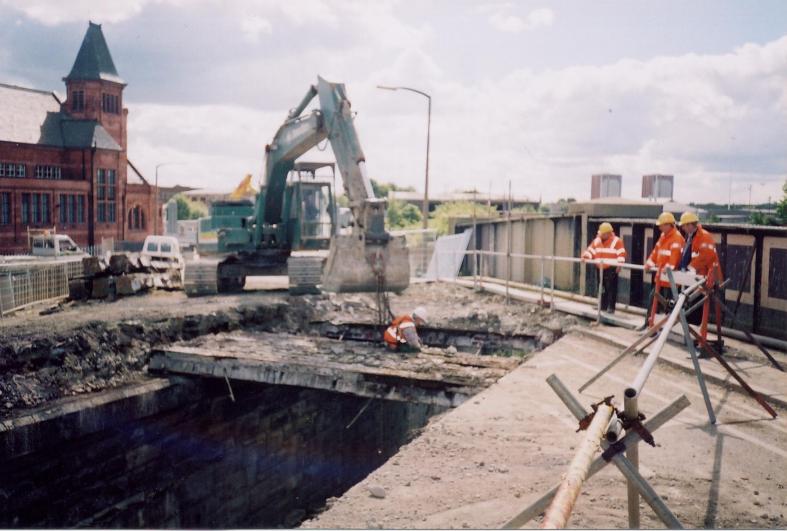
East end MGL using a 35t excavator to lift out the smaller girders on the side span - looking on Simon Boddy, Ian Robinson and Ian Watson
During the course of the demolition Barron Demolition Ltd experienced finanacial difficulties and were eventally replaced by MGL Demoltion who took over the contract to complete the demolition works.
Deck being cleared - concrete being removed from the buckle plates between the beams
Deck buckle plates being cut free ready to be lifted out.
Top section of the edge girder cut free and lifted out.
Bottom section of the edge girder cut free and lifted out
Buckle plates cut and lifted out.

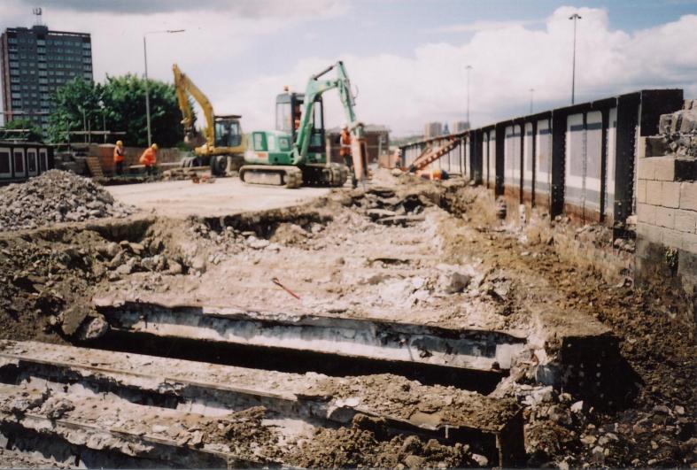
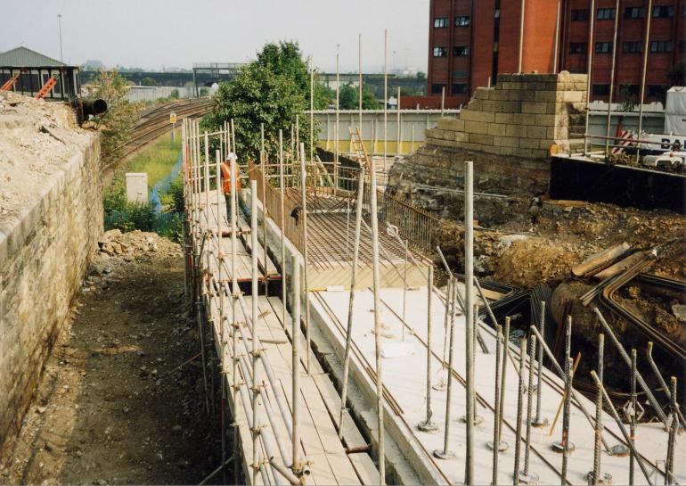
West side span with giders and buckle plates removed - access scaffold installed to enable works on the abutment.
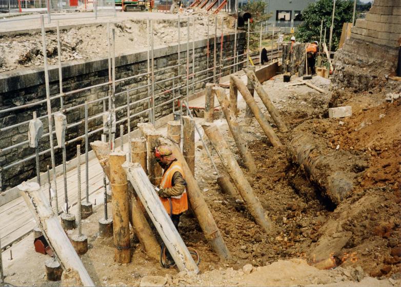
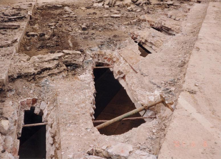
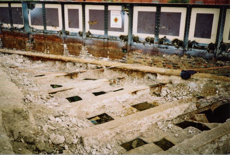
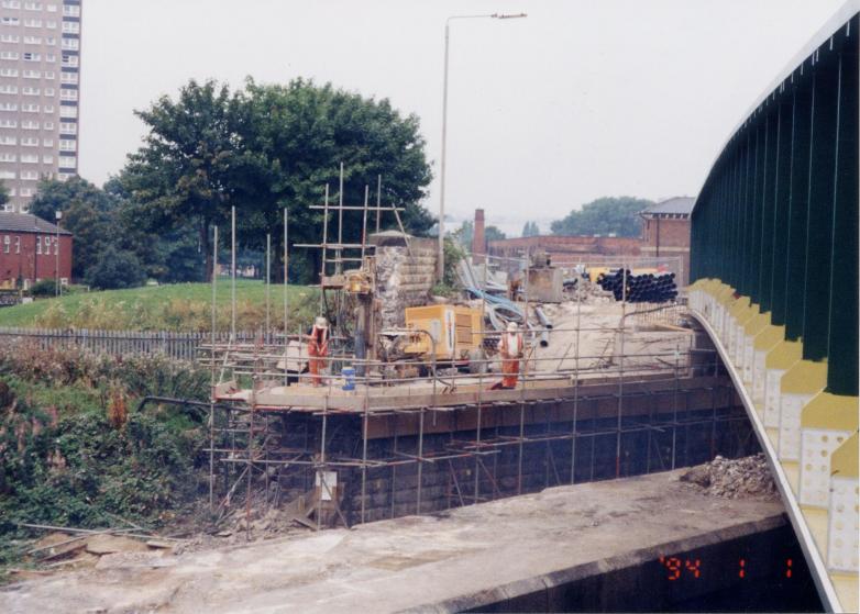
East abutment piles being cut down - steel outer case being burnt and grout broken down.
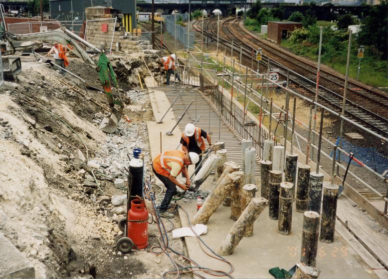
West Abutment blinded - steel fixing underway on the north section as piles are being cut down.
East Abutment blinded - piles broken down and steel fixing started.
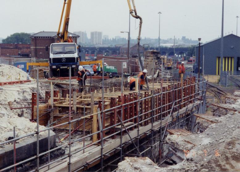
North west section of the bridge abutment being concreted.
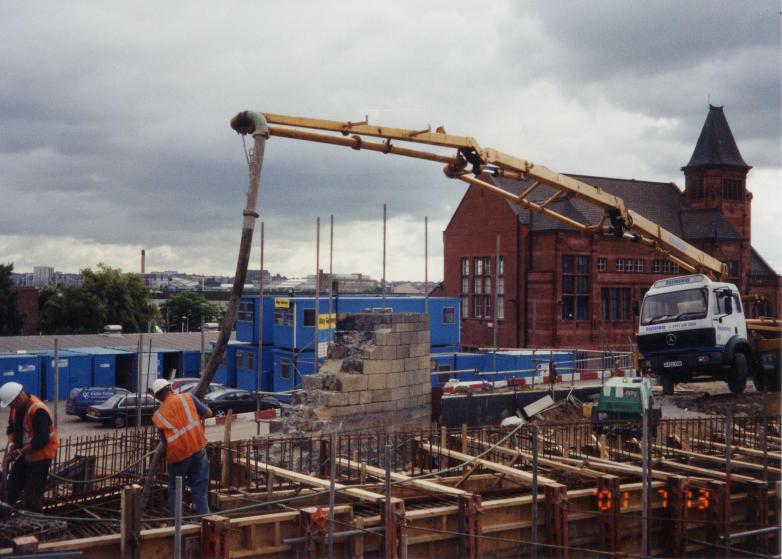
North East corner of the abutment being concreted.
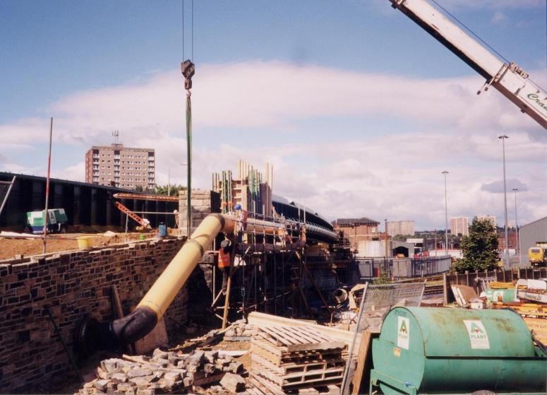
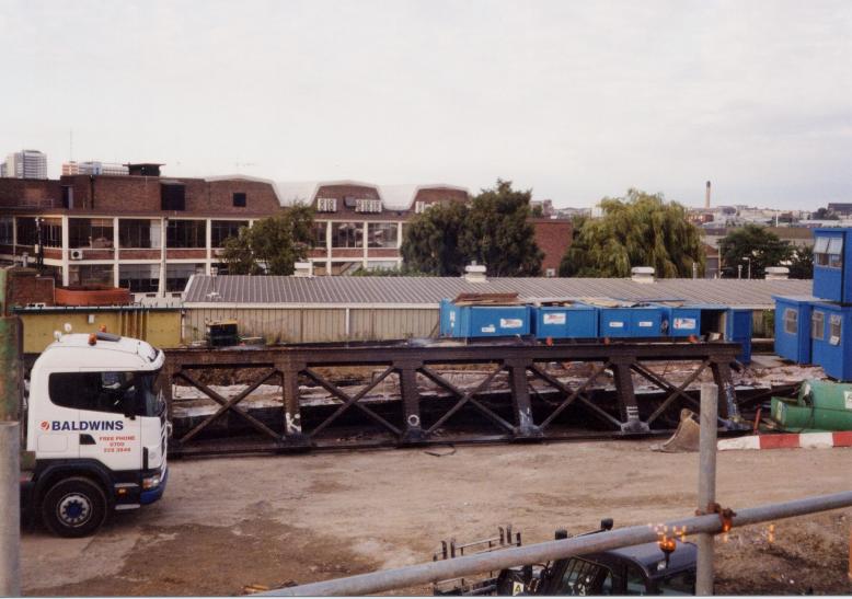
To enable the central section to be demolished a 20m long temporary plant access-bridge “Mabey Support Quickbridge” was installed on the 15th July 2001(following much pain sorting out a Form C) this enabled MGL access to demolish the central span.
Temporary Mabey Quick bridge being installed to reach the central deck area for demolition.
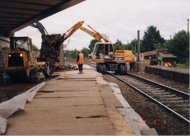
With access available MGL started the removal of the existing deck surfacing down to the backing concrete level of the jack arches, leaving them structural intact and exposed ready for removal in the 30hr possession on Sunday 22nd July 2001.
At the beginning of the 30hr possession a full crash deck was installed to provide protection to both the permanent way, signalling and telecom equipment. The crash deck took the form of timber railway sleepers with a plywood covering, this same arrangement was used successfully during the first phase of demolition works on the West side span and provided ample protection to the railway infrastructure. With the crash deck track protection in place the demolition sub-contractor was able to access the area under the jack arches with small articulated dump trucks.
During a 30hr possession the track was fully sheeted with sleepers and plywood.
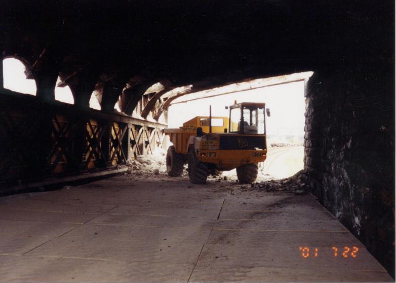
Small Dumper running on the boarded area with the arches being broken out from above.
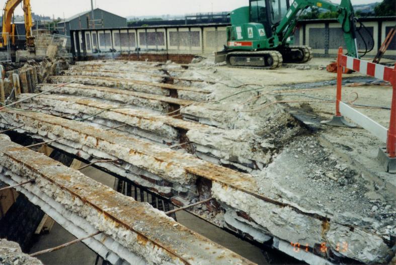
At high level a JS160w rubber tyred excavator gained access to the central area of the structure via the temporary quck bridge. Working along the length of each beam the the excavator fitted with a hydralic breaker "pecker" smashed through each of the arches - with the falling rubble landing in the back of the dumper located below. The excavator worked along the length of each beam - working th breaker into the flanges of the girders to remove as much brick (weight) from each girder. The excavator worked across the span until eventally moving back up to to the quick bridge leaving the girders insitu ready for a further 30hr railway possession booked for the following weekend.
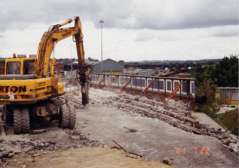
Wheeled excavator working on the bridge deck breaking out the arches - Note the Temporary props on the edge girder.
Girders still in place with the arches broken out and fenced off at the end of the possession.
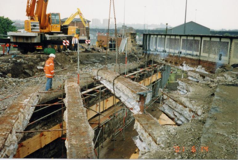
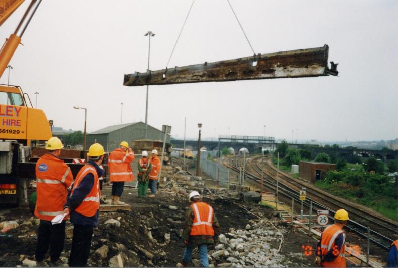
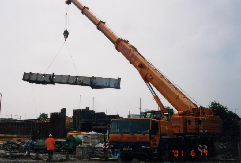
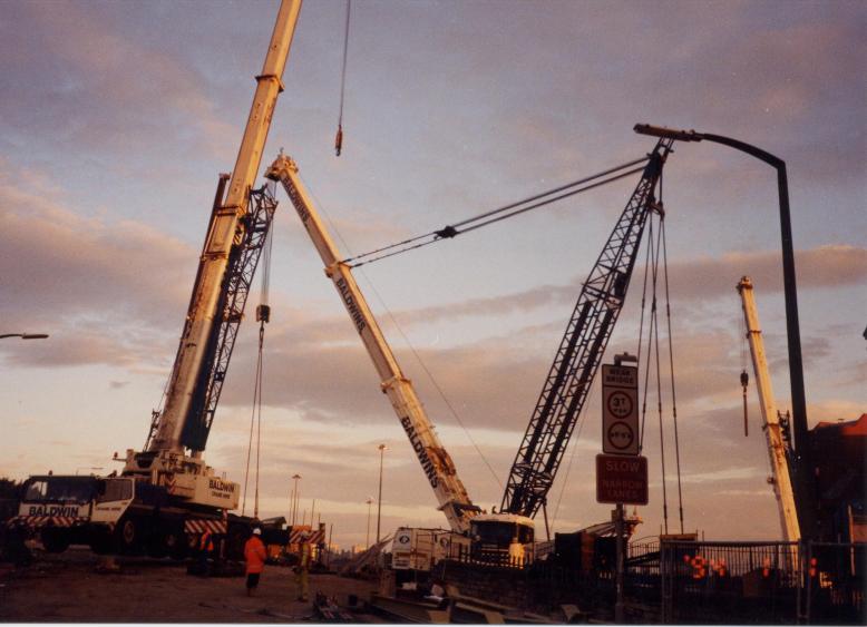
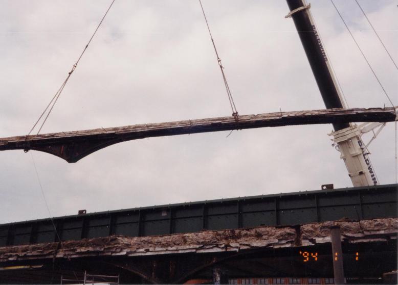
Following on from the successful removal of the central span jack arches a further 30hr track possession was undertaken on the 28th July 01 to remove the girders and part of the western trestle. The temporary quickbridge was also removed during this possession. The demolition contractor MGL utilised a 500t crane rigged in the site compound prior to the possession to remove the redundant girders. Each girder varied in thickness down to the trestle connection point this combined with the brick left from the jack arches made setting and balancing the chains quite diffcult. The central span steelwork consisted of 6nr 28t internal girders, 1nr 5.5t redundant gas main 24inch and 1nr 18t main edge girder. The existing girders span from an internal eastern leaf pier to a western steel leaf trestle. The girders were connected to the trestle via a haunch steelwork down-stand. This arrangement introduces a number of problems to the removal of the steelwork. Due to the unbalanced loading caused by the haunch down-stand great care was exercised with regard to slinging the girders. Only when the girders are correctly balanced can the haunch be cut free at the head of the trestle. A tower scaffold was utilised by the demolition contractor to access the girders to attach the chains and burn away the bolted connection at the top of the trestle. The tie bars between the girders could then be severed leaving a freestanding girder. On completion of the possession enough of the old structure had been removed to enable the Phase I steel girders to be erected.
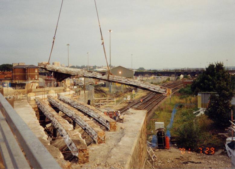
30hr possession - crane lifting out the bridge girders.
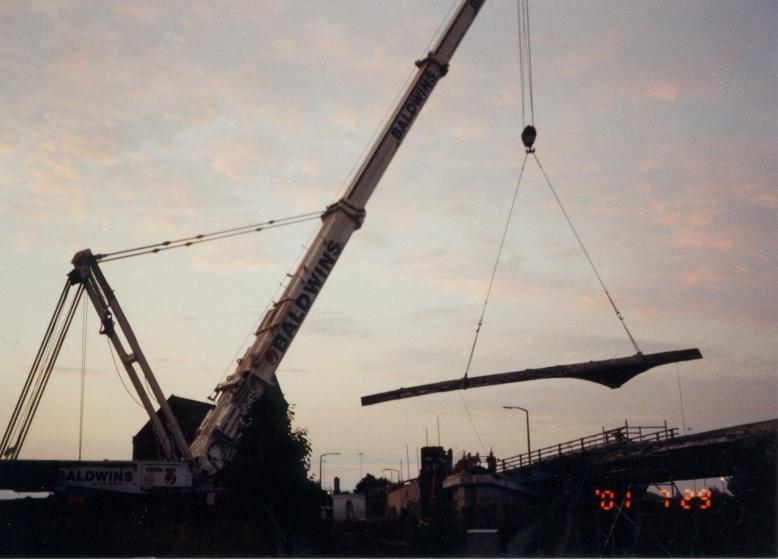
Baldwins crane lifting out the central girders.
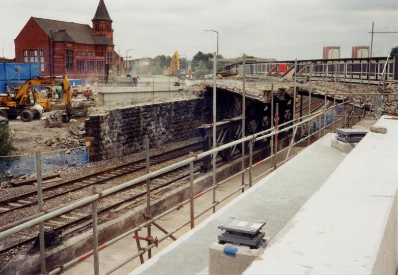
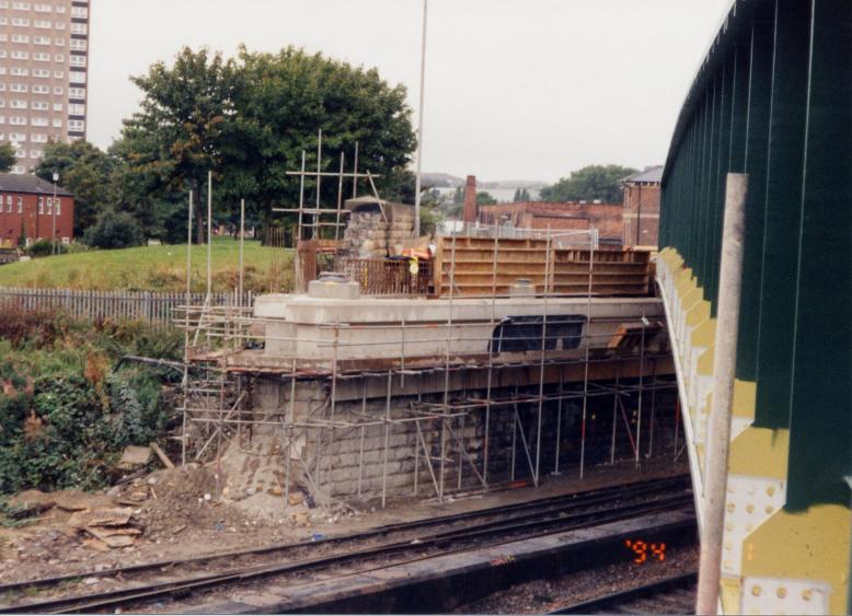
View after the possession - showing the North East and West set up with the abutments set.
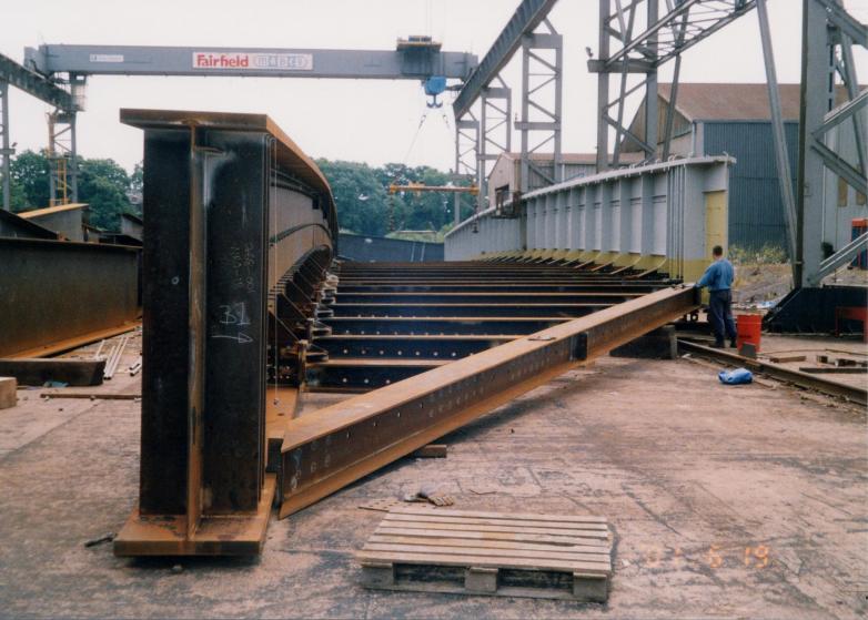
Mabey Bridge - trial erection in the Yard.
In the middle (15th) of June 2001 Fairfield Mabey commenced the delivery of the new bridge steel work to site. The girders were delivered in two halfs with each girder being set up into postion ready for on site welding and final site top coat painting.
Bridge beams brought to site and being set up in the compound ready for welding and painting.
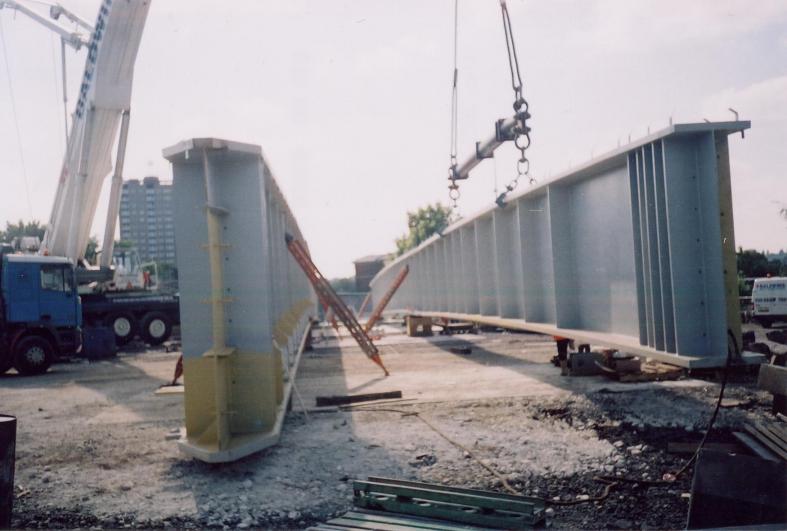
Work on the Main girders progressed well through out June and July - warm dry weather assisted with progress to firstly weld the main beams together and them apply the protective paint system to the girders. Works also progressed on the completion of Phase 1 of the abutments construction by the start of August 2001 the bridge was ready to accept the Phase I steel work.
North and central girders being set up - welding and painting in progress.
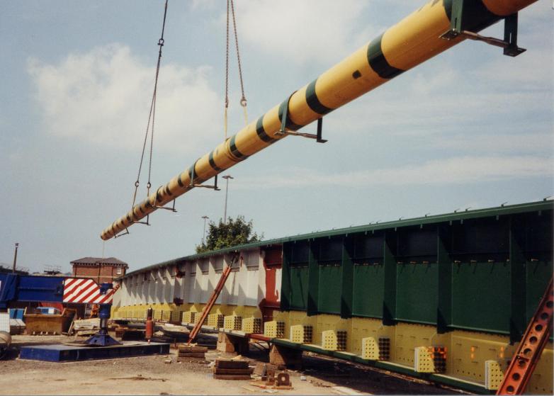
New gas main being lifted into position on the outside of the North Girder.
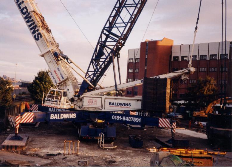
1000t crane being built up in the site compound.
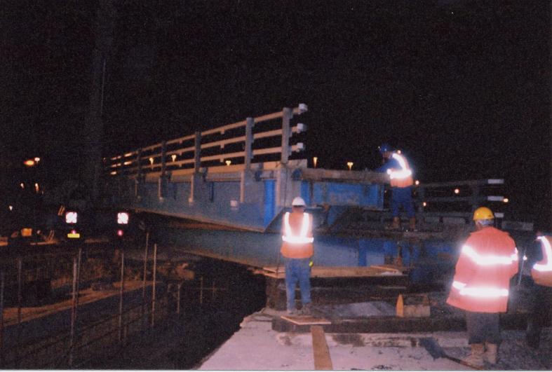
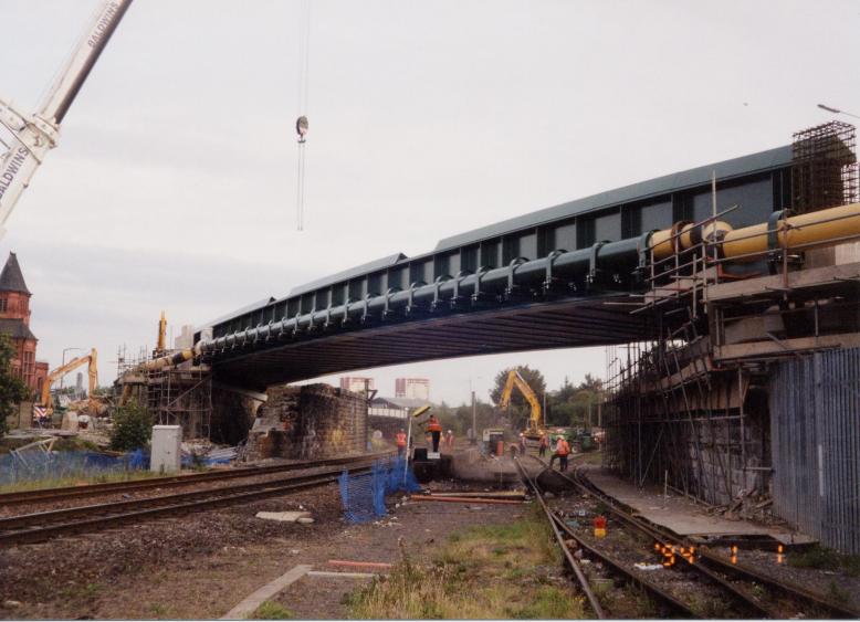
A 30hr railway possession was booked by May Gurney to commence on the 5th Aug 01 to lift into position the Phase 1 steelwork. During the possession period protection of the railway infrastructure was via a pre-programmed T(iii) possession of the TJC3 main lines and a T(iv) possession of the sidings line into Engine Shed Junction. The work to install the girders was carried out by Fairfield Mabey under May Gurney supervision. The main crane lifts took place in the May Gurney site compound where a 1000t crane located on piled foundation pads was used during the possession to lift in the North and Centre girders. Two smaller (120t & 50t) cranes were located on either abutment and these were used to lift into position the cross girders. During the day shift (3rd /4th August 2001) prior to the main 30 hr possession the 1000t crane was assembled with a (80t support crane) in the site compound with all the works being done during normal working with no part of the crane supplied by Baldwins coming within three metres of the nearest “live” running rail.
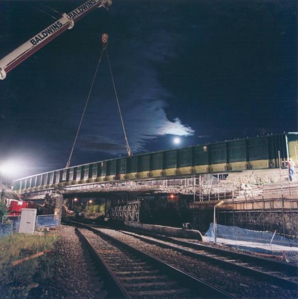
Central girder being lifted into position.
Cranes lifting in the main girders.
David Millar worked on the weekend shift installing the intermediate cross girders and trimmer beams. The first item FFM tried to install was the East abutment trimmer beam, which was found not to connect up with the central bearing on the abutment. It was found that the trimmer beam bearing did not pick the bolts on the trimmer beam bolt holes. It as decided to put the trimmer beam on timbers baulks and jacking it up post possession to reset the bearing.

Girders set in position - temporary props supporting the girders as the intermediate girders are lifted in to place.
During the 30hr possession the central girder was lifted into position first and locked off using temporary RMD bracing bolted into the abutment once fixed the 1000 crane was un-hooked and slewed back over the North Girder. The 1000t crane lifted in the North Girder and sat it on to the bearings. The support cranes located either side of the abutment fitted the intermediate internal cross girders and also temporary works RMD "K" bracing used to lock the bridge girders into position.
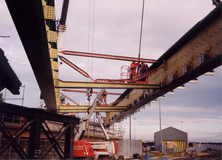
Intermediate girders being lifted into place and bolted up. Note the the K bracing temporary support.
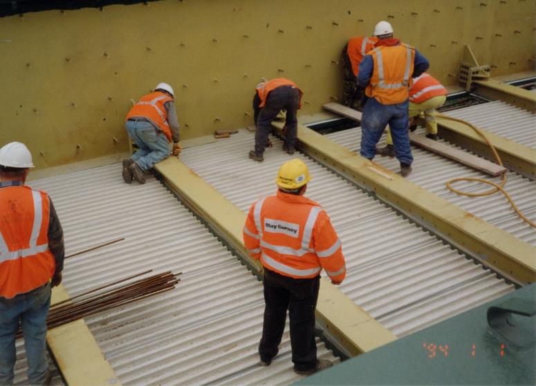
Following installation of the cross girders Cairn Cross Civil Engineering Ltd started installing the GRP permanent formwork supplied by EMJ plastics. The panels were laid on to a butyl rubber mastic seal and self-adhesive foam tape. The tape and the foam were attached to the cross girders and along the edges of the girders prior to being lifted into place. Placing of the panels will commence over the Up and Down Midland Rails immediately after the cross girders have been placed. All the panels in the northern span were laid during the possession with the final section of panels being laid over the side spans out with the area affected by the possession.
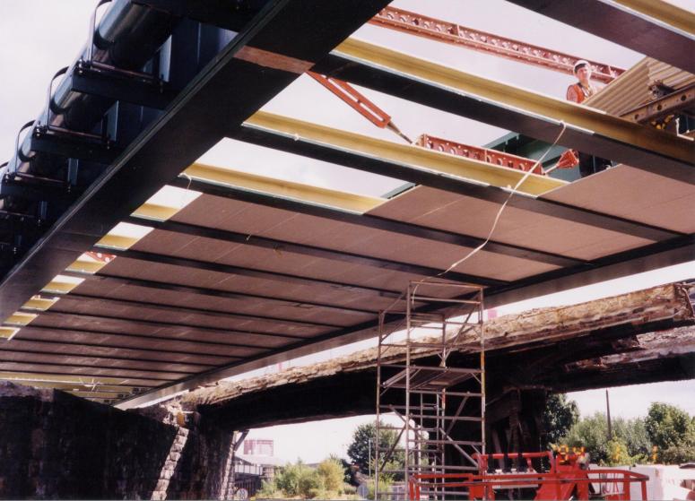
Cairncross Civil engineering fixing GRP - Permenant formwork (EMJ)
With the Phase I steel -work installed - Fairfield Mabey turned to the off loading of the Phase II steel work which arrived on site for off loading in the site compound area. The 1000t crane lifted and set up the two halves of the final southern girder locking it into position ready for welding and final top coat painting.
Southern Main Girder being delivered to site and being set up for welding and painting.
New Gas main on north side of the bridge being connected up ready and made live to make the Gas Main redundant on the Existing southern girder.
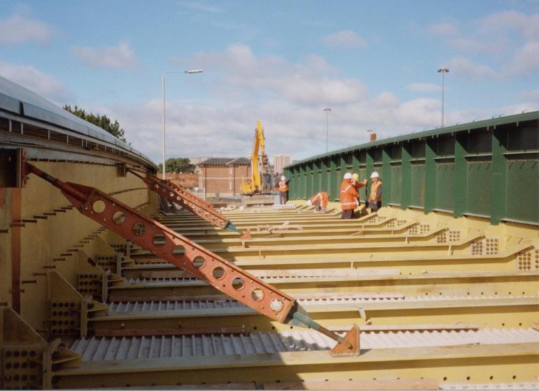
Following on from the possession to install the northern girder (with the gas main attached) work progressed on the connections either side of the bridge. Work also progressed on the northern span with the final section of GRP panels being installed over the Engine Shed Junction siding section of track. With the GRP fully installed the reinforcement started being installed. The reinforcement in the bottom layer of the bridge deck passed through the cross girders -Mott MacDonald designed the reinforcement to be mild steel. The smooth nature of the bar made it easier to install through holes in the cross girders, however mild steel production and supply turn out to be a problem, as although cheaper than high tensile steel bars, the reinforcement supplier (ROM) only carried out a production of mild steel once a large enough order book was available to undertake a production run.
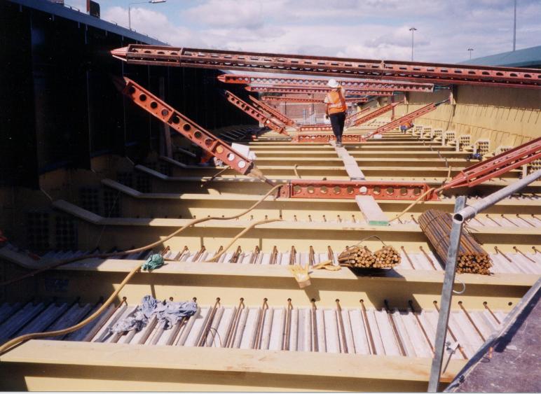
North Deck - steel fixing underway - note the Mild steel reinforcement running through the transverse girders.
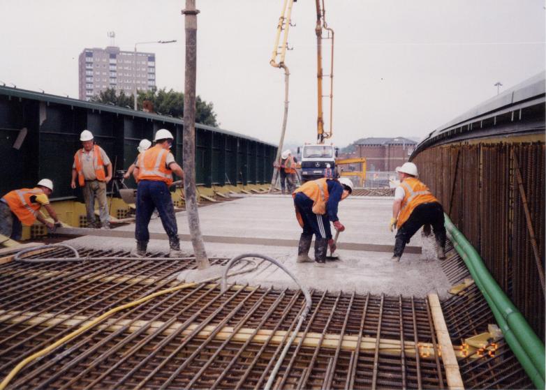
North span being concreted
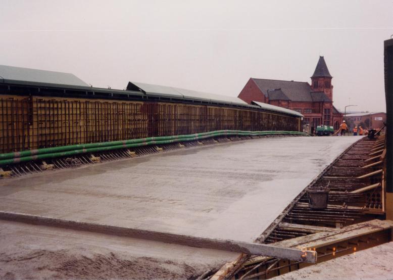
North deck section being cast and screeded off.
Work progressed throughout August the project critical path - gas main diversion works was completed in the week prior to a 30hr possession booked to remove the southern section of the old deck. The diversion of the gas main made the pipework on the outside of the southern girder to be made redundent and thus ready for removal.
Work also progressed on the abutment bearing shelves with the next section being cast and "stop ended" up to the close proximity of the existing structure. Following a review of the Phase I demolition works by the site team and the designers it was agreed that it would be possible to fill in behind the East abutment and stone leaf pier such that a small excavator (17t tracked with hydraulic breaker) could gain access to the centre section of the deck this negated the need to install a temporary access bridge.
Following on from this possession the rubble material was removed from between the abutment and the pier with the material removed from site. At deck level the Northern side of the bridge deck was set up and cast, during normal working.
With the demolition of the last of the existing bridge structure, the final section of the abutments became fully available for installing the last of the mini piles and completion of the final section of the bearing shelf for the southern half of the new structure. From the start of September 2001, I started pulling together method statements and information for MVL3 Bridge 81 Upper Brow Road in Huddersfield (see Project 12). I met up with Terry Loney who was to become Foreman on a number of projects with me in the next couple of years (not that a knew this at the time).
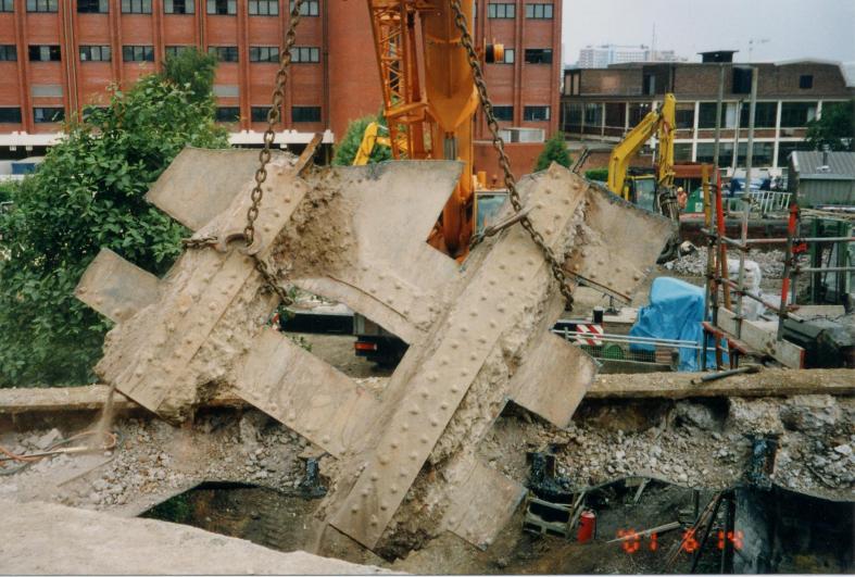
David Millar worked on the second shift of the possession supervising the 400t LTM 1400 undertaking the demolition which was set up in the site compound to enable the final section of existing structure girders to be removed. During the possession the existing gas main (11t) was removed along with 4nr (24t) internal girders, 2nr (12t) internal girder, 1nr (14t) skew girder, 1nr (27t) main edge girder (cut into smaller lifts), 1nr (9t) edge girder and 1nr trestle. The existing internal girders span from the masonary eastern leaf pier to a western leaf trestle. The external edge girder was cut into a number of sections to enable them to be cut free and loaded out into the site compound.
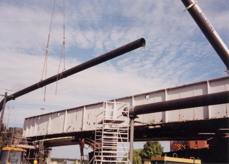
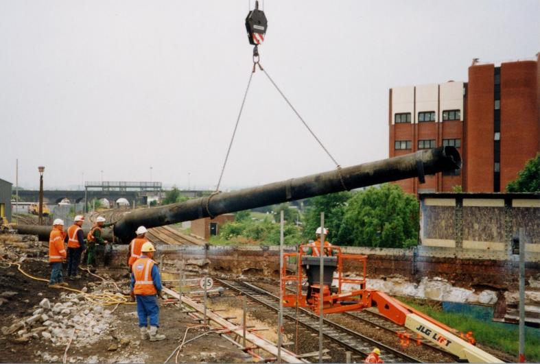
30hr possession - Existing redundant gas main cut and lifted out.
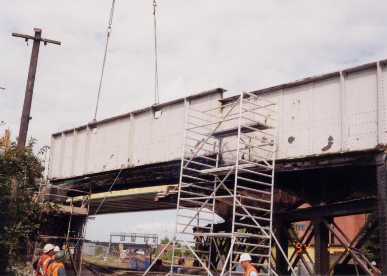
Bridge edge girder cut free and being lifted out - access for cutting via tower scafold.
Central set of girders being lifted out by Crane. Crane lifting over the North Deck.
Steel tressle lifted out and stockpiled in the Yard.
Following on from this possession the rubble material was removed from between the abutment and the pier with the material removed from site. At deck level the Northern side of the bridge deck was set up and cast, during normal working.
With the demolition of the last of the existing bridge structure, the final section of the abutments became fully available for installing the last of the mini piles and completion of the final section of the bearing shelf for the southern half of the new structure. From the start of September 2001, David Millar started pulling together method statements and information for MVL3 Bridge 81 Upper Brow Road in Huddersfield (see Project 12). David Millar met up with Terry Loney who was to become Foreman on a number of projects with me in the next couple of years (not that a knew this at the time).
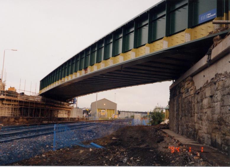
View on the North Girder - note the new live gas main.
West abutment southern section being piled.
During a possession on the 1st September 2001 - David Millar worked on the second shift breaking up and removing the existing masonry eastern leaf pier. During the possession the track was protected using a series of sleepers plywood - the demolition of the pier was undertaken using a 13t wheeled excavator fitted with a hydraulic breaker and tracked dozer. The wheeled excavator was able to run on the track bed to break into the masonary and push the pier over once opened up the rubble fill centre was broken open and pushed into the dead are infront of the east abutment for removal into the site compound.
Follow up possession being undertaken to remove the redundant side span stone pier.
Old stone pier demolished and cleared up.
Piling being undertaken on the Southern half of the East abutment.
Steel reinforcement and Formwork being set up.
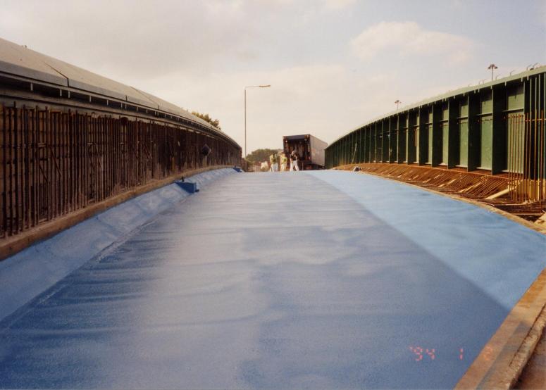
North Deck - spray waterproofing bu Pitchmastic PMB.
North Deck - sand carpet laid on the deck - and kerbs in progress.
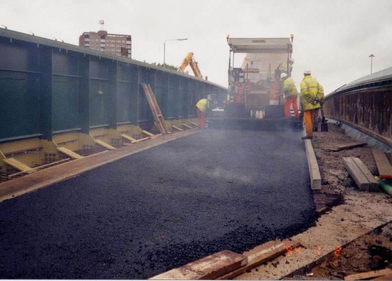
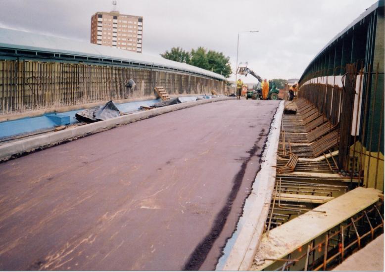
Surfacing being laid on the North deck.
With the abutments completed and steelwork southern girder welded and top coat painted ready for lifting during the mid September 2001. A further 30hr possession was taken on the 14th September 2001 to install the southern girder along with the internal girders and GRP once again David Millar worked on the second shift during the Sunday to install the GRP permanent formwork. The main girder was installed using Baldwins 1000t crane located in the site compond again supported with two smaller 160t cranes located either side of the bridge behind the abutments to lift in the internal cross girders and temporary works prop bracing. This possession turned out to be the final possession David Millar worked on this project as on the following Monday he started to set up site at Upper Brow Road for MVL3 Bridge 81.
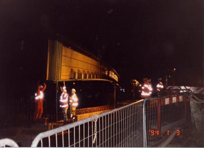
Southern Girder being lifted in to place during 30hr possession.
Simon Boddy looking after the installation of the GRP on the Southern deck.
GRP fixed on the deck - Temporary bracing fixed to the girders.
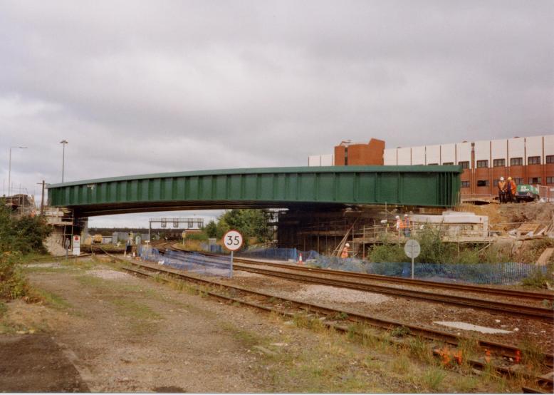
View on the South Girder.
The work at Nineveh road continued until the start of 2002 with the southern deck being cast and road construction being installed following application of spray waterproofing. The main bridge girders were internally infilled with reinforced concrete, stone work was reinstated on the abutments, street lighting installed, bridge expansion joints, safety barriers, kerbs and footpath were all installed. During a number of short 8hr possessions - touch up painting was completed along with the sections of copings over lifting points.
Southern deck being cast.

Under the bridge the abutment stone work has been rebuilt and pointed - really good job.
In the central area - polystrene blocks being used to reduce the weight of the barrier. Steel being fixed in the central deck area.
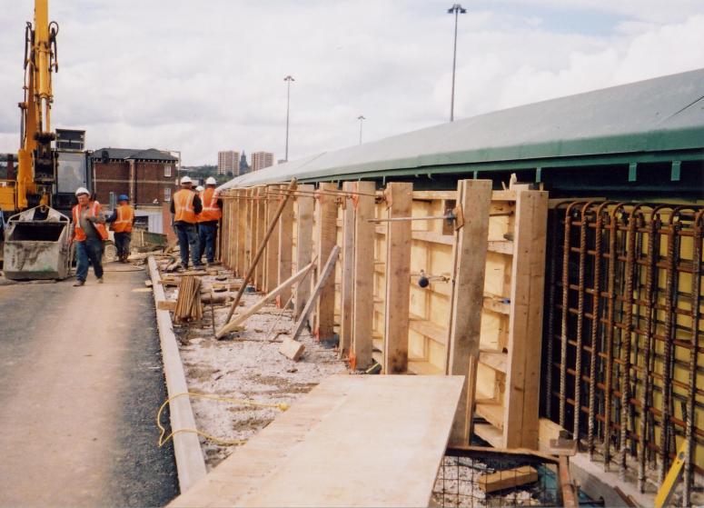
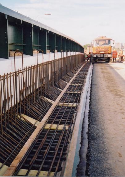
Formwork being set up along the length of the outside girder with the steel reinforcement fixed and set.
Concrete infill cast along the length of the outside girder.
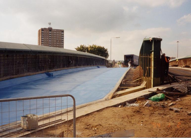
Southern deck cast and sprayed with waterproofing by Pitchmastic.
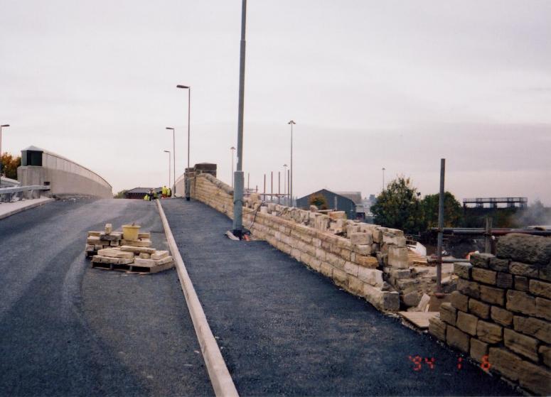
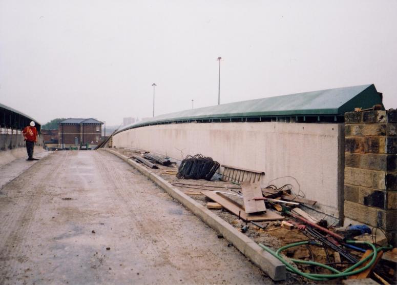
Approach roads being constructed - walls being rebuilt and lighting installed.
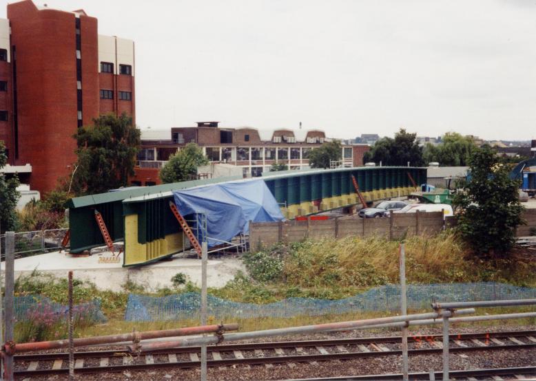
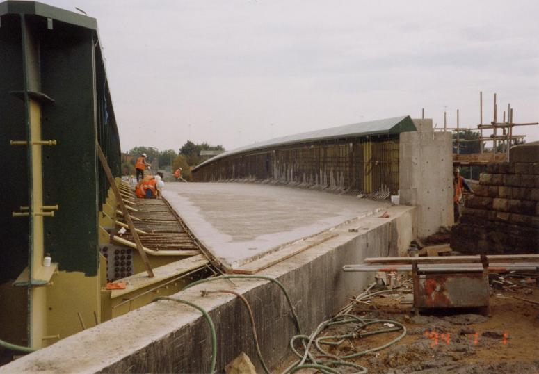
View over the Northern Deck following completion of the kerbing and surfacing.
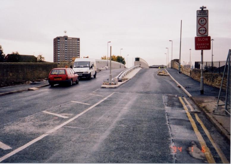
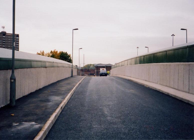
View on the approach to the bridge being prepared for opening.
May Gurney - Project Team
Martin Holmes (Construction Manager)
Ian Watson ( Site Agent )
Simon Boddy ( Sub- Agent )
David Millar ( Sub- Agent )
Andy Finnerty ( General Foreman )
Rob Proctor (Works Manager)
Ian Robinson (Engineer)
Page under construction...
| 