|
Dish Hill Flyover refurbishment project Summer 2005 as part of the A1 Darrington-Dishforth DBFO scheme- this project was undertaken in two phases. The first phase involved the refurbishment of the structure at deck level. The bridge deck carrying the A162 at high level over the bridge closed to both traffic and pedestrians to enable strengthening to the cantilever slab with an in-situ concrete slab and parapet beam cast on top off and in board of the existing parapet beam to act compositely. The existing parapet masking walls, were replaced with new masking walls structurally connected to the existing abutments. A new parapet (N2 Type) was installed on the newly constructued parapet beams. The existing asphaltic plug joints were also replaced with BEJ type joints with rubber inserts. Phase II - was undertaken following full closure of the A1 below the structure, following completion of Phase I works. The full closure was required to provide access to enable the structure to have additional plan bracing installed to the main beams of spans 2 & 3. The structure was also fully repainted, following grit blasting and primer application. Several areas of spalling concrete were also repair to east / west abutments, trimmer beams and to the cantilever parapets especially above piers.
Dish Hill Flyover (HA reference number A1/288.50) was constructed between 1960 and 1962 as part of the £486,000 (1960's price) Brotherton Bypass Scheme with the original construction work being undertaken by Harbour and Genral Works. The bridge has been subject to a high degree of settlement over the years this culminated in the central pier being replaced in 1987 and the east and west piers replaced in 1991.
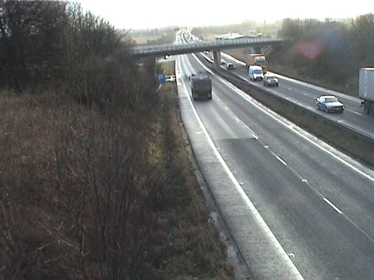
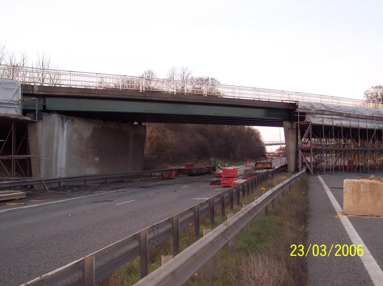
E57 Dish Hill Flyover with the busy A1(M) running under the structure.
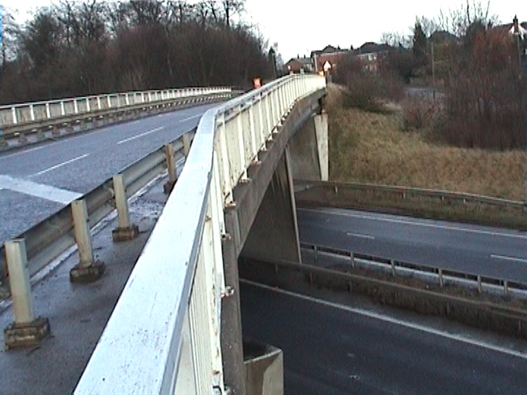
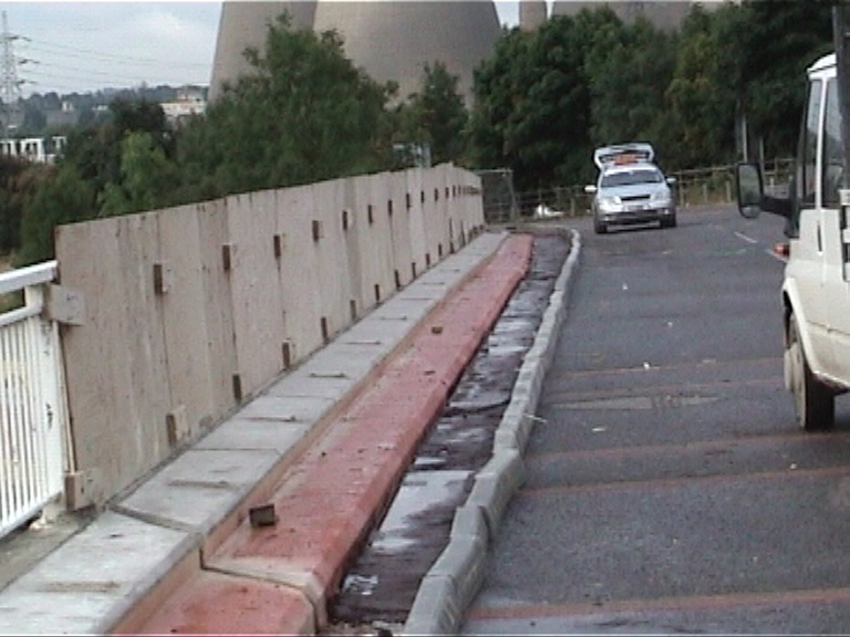
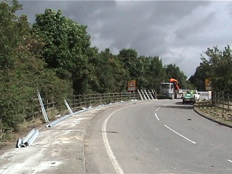
The bridge deck prior to refurbishment showing the existing non standard parapet and safety barrier arrangement.
Under the Darrington to Dishforth (D2D) DBFO contract(Existing Structure 57), Dish Hill Flyover was refurbished with the old A1M (running under the bridge) de-trunked. Following completion of the reburbishmnet works the structure was handed over to North Yorkshire County Council (NYCC). The maintenance of this structure following handover became the the responsibility of North Yorkshire County Council running for the whole concession period of the DBFO contract.
Existing Structure Description -
The four span simply supported structure is formed from universal steel beams of different sizes acting compositely with a 178mm deep reinforced concrete deck slab incorporating cantilevered parapets. The bridge has high skew spans measuring 16.77m at the west end, 21.56m over the northbound carriageway of the existing A1(M), 24.92m over the southbound carriageway and 14.38m at the east end. All spans are measured between centre lines of the bearings. The A162 carried by the structure comprises a 2 lane slip road, with a carriageway varying in width from 5.90m at the southern end to 6.70m at the northern end. The structure has a skew of 50.5 degress and has a total length of 77.63m measured between centre lines of the abutment bearings, with an overall deck width of 10.67m. The minimum headroom over both the northbound and southbound carriageways of the A1 is 5.11m and 5.12m respectively. The structure has three reinforced concrete cantilever leaf piers, tapering in cross section towards their base. The east abutment is of the skeleton type formed of three individual columns on a spread footing. The west abutment is similar but with four individual columns on a piled cap. The bridge deck is fixed at the east and west piers and free at the abutments and central pier. All spans are structurally independent from one another with expansion joints existing over each pier and abutment. The bearings are laminated rubber pads at the abutments and at the central pier allowing rotation and translation in all directions. There are spherical bearings at both the east and west piers allowing rotation but no lateral translation. The existing parapets were Type P4 steel with three horizontal rails and vertical infill panels with a tensioned corrugated safety fence used to protect the parapets.
An assessment of the existing cantilevered slab for accidental wheel loading to BD21/01 and BD 37/88. and associated parapet loading to IRRRS showed that the slab has insufficient bending capacity. To overcome this structural deficiency a new concrete haunch and parapet beam were designed to be structurally connected by reinforcement grouted into the existing deck slab.
Assessment of the main beams for collision loading to BD60/94 highlighted that the beams had insufficient lateral bending capacity to resist the loads. To overcome this problem a design was produced to increase bending capacity by structurally connecting plan bracing to the bottom flanges of the main beams. To transmit the loads down to the substructure from the main beams, additional bearings were designed to be added to compliment the existing bearing system. Assessment of the existing bearings for collision loading to the two central spans to BD60/94 showed that the bearings had insufficient horizontal capacity to resist the loads. This deficiency was remedied by the provision of an additional fixed bearing at each end of the two central spans at the east and west piers, and a centrally positioned guided bearing on each of the two spans at the central piers. These bearings allow the same degree of articulation as the existing bearing system.
Assessment of the existing parapet system showed that it does not comply with the Intermediate Requirement for Road Restraint Systems. The parapets did not comply with the strength requirements or dimensional requirements of BD 52/93. This deficiency was remedied by the replacement of the existing parapet and safety fence with a new, 1.0m high, aluminium parapet of containment performance class N2 as specified in the IRRRS. The existing parapet masking walls, constructed as part of the 1987 central pier works required replaced with new masking walls to accommodate the proposed parapet.
A Principal Inspection undertaken in 2000 highlighted localised concrete spalling and minor reinforcement corrosion in the original deck soffit, transverse diaphragm beams and cantilever due to water leakage, particularly beneath the existing expansion joints. The structure was to be inspected as part of the remedial works with concrete repairs undertaken as Identified. The asphaltic plug joints on the bridge were to be replaced with Britflex Nosing Joints with rubber inserts - to improve flexibility of the structure and also stem the flow of water from the joints.
The proposed remedial works consist of the following- Phase I - Closure of the A162 at high level over the bridge to both traffic and pedestrians to enable strengthening to the cantilever slab with an in-situ concrete slab and parapet beam cast on top of and in board of the existing parapet beam. The two will be stitched together to act compositely. The existing parapet masking walls, will be replaced with new masking walls structurally connected to the existing abutments. A new parapet to IRRRS (N2 Type) will be installed on the new parapet beam. The existing asphaltic plug joints are to be replaced with BEJ type joints with rubber inserts.
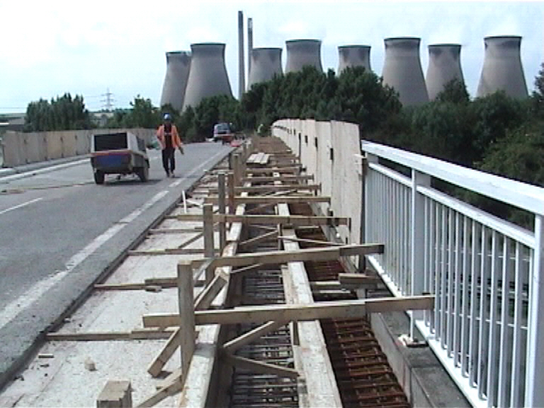
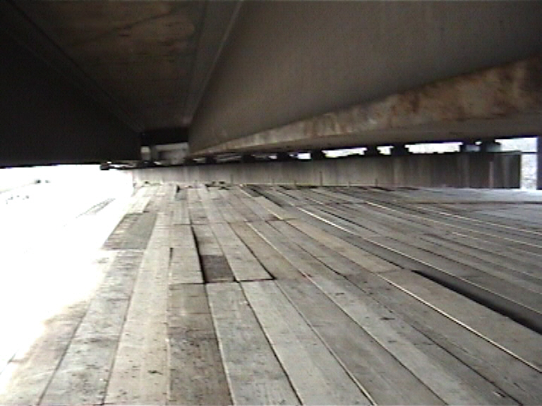
Phase I works started on the 20th May 2005 with the full closure of the A162, a push test was undertaken on the existing parapets prior to timber plywood sheeting being attached to act as a temporary screen to prevent material falling to from the deck during the course of the refurbishment works. This enabled the parapet replacement works to be undertaken with the busy road (A1M) passing under the bridge unaffected by the works. With the temporary protective hoarding in place - Balmer Lindley (Safety Barrier and Parapet systems) removed the existing safety barriers over the bridge.
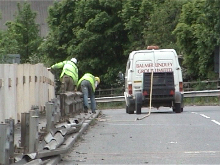
E57 Dish Hill Flyover - Balmer Lindley removing the the existing safety barrier in the footpaths.
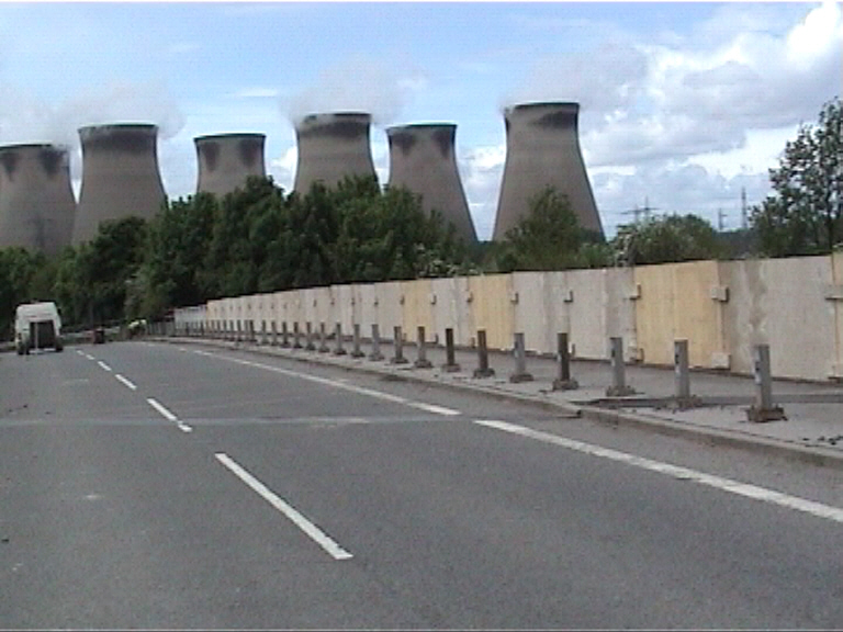
Temporary Hoarding being installed to the existing parapet fence following closure of the bridge on the 20th May 2005.
With the safety barrier removed Sword Construction (employed by RMG to undertake the main civils works) utilised a 360 deg excavator to dig the old abutment masking walls and started to remove the existing kerbs and footpaths on both sides of the structure. Swords also prefabricated the parapet ground beams of the bridge deck ready for installation once the deck had been surface prepared. On the 10th June 05 a successful trial was undertaken on the proposed material (Hilti Hy 500) being used to anchor the stainless steel bars as part of the new composite reinforced concrete parapet.
Swords removing the existing footpath, kerbs and services
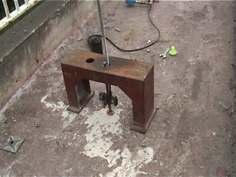
Hiti 500 pull out tets being undertaken on the deck to prove the epoxy material used to fix the new parapet to the existing bridge deck.
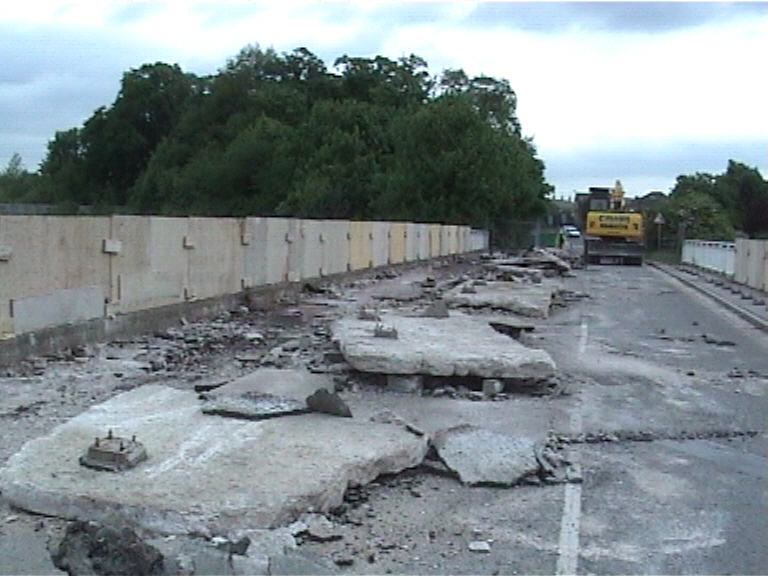
On the 13th June 05, with works progressing off the deck to prefabricate the reinforcement cages for the parapets, Delmar flooring (and SPE undertaking the grit blasting) used heavy duty Von ark surface preparation equipment to remove the existing spray applied "eliminator" waterproofing over the areas to be covered by the new concrete parapets. The surface preparation works to five days to complete including a days shot/grit open blasting to the existing parapet upstands. With the surface preparation completed the designers inspected commented on the good condition of the deck concrete.
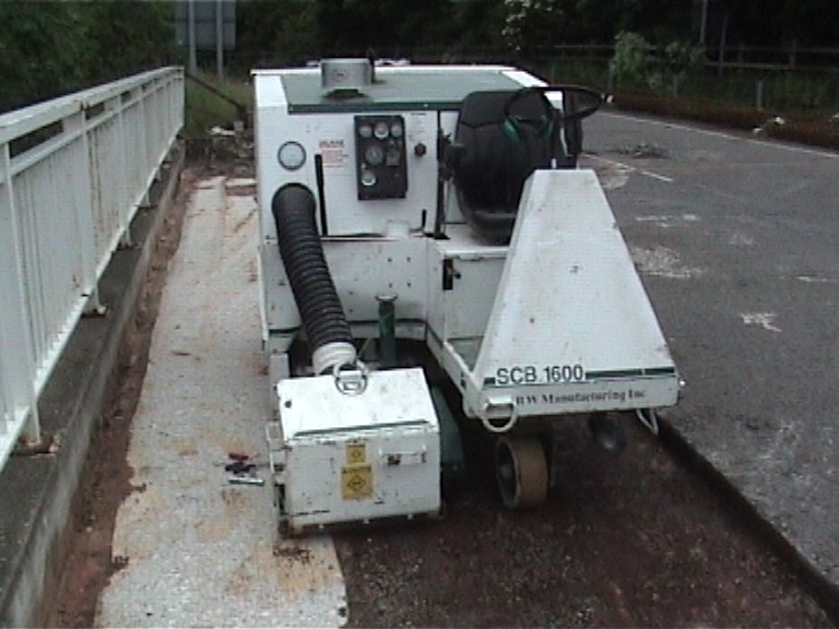
Ride on Von-arks Machine Delmar flooring removing spray applied waterproofing.
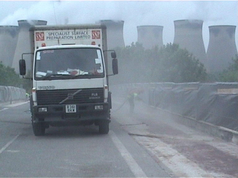
SPE grit blasting the verical face of the parapets to provide a key for the new reinforced concrete parapet.
Swords begun installing the prefabricated cages for the parapets on the 17th June 05 and these were cast in sections through out the remainder of June and July 05. Swords also cast the four corner wingwalls at the back of the abutments these incorporated N2 bolt clusters to carry the new alumnium parapet off the end of the deck.
Parapet strengthening works - reinforced concrete parapets being constructed.
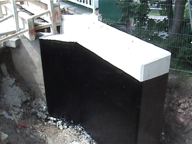
New wingwall being constructed at the back of the abutment.
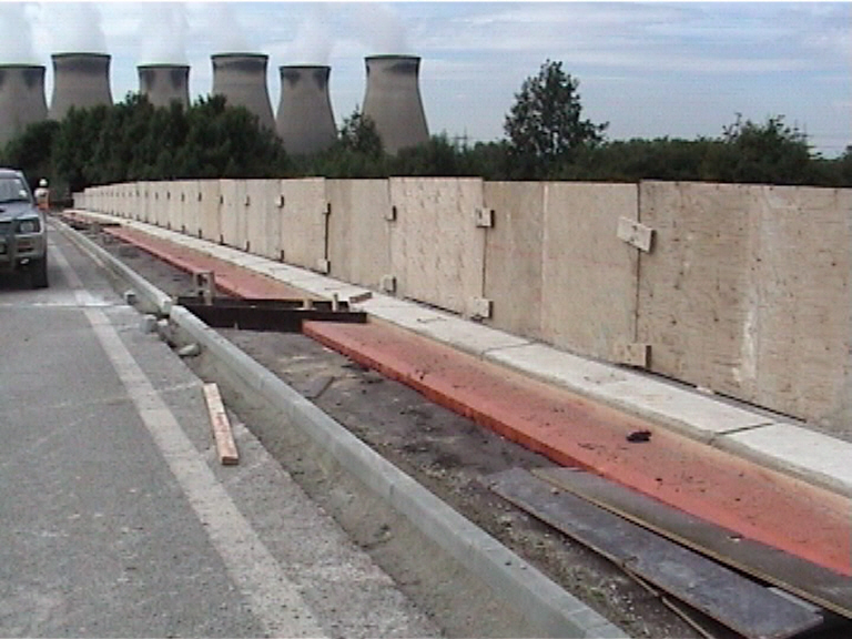
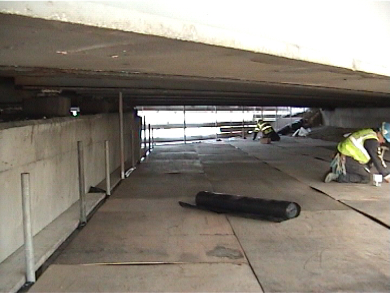
On the 1st Aug 2005 - Stirling Lloyd applied spray applied "eliminator" waterproofing to the new concrete parapets with a 100mm lap being achieved onto the existing waterproofing on the deck. On the 4th August 05 - Aggregate Industries laid 20mm red sand carpet on top of the waterproofing to act as a protective marker layer for any future works being undertaken in the footpaths.
Parapets on the bridge completed and spray "eliminator" waterproofing applied by Stirling Lloyd
20mm red "sand carpet" waterproofing protection layer being laid by AI.
With the sand carpet installed work progressed on the Kerbs on the structure - all the kerbs were laid out, installed and "backed up" on the 5th August 05. With the kerbs installed Swords installed formwork at each of the bridge expansion joints to enable the footpath concrete to be laid to the correct profile. Working to sizes provided by USL a series of box outs were created this work took three days to complete and although the box outs were not large they were difficult to hold in place due to the large sqew on the bridge deck.
Kerbs laid out ready to be laid
Kerbs installed - with formwork to create expansion bridge joints.
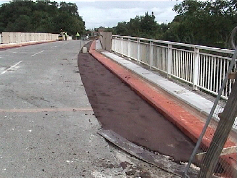
The footpaths were eventually concreted (following much discussion with the HA about Ducts) on the 10th August 05 using air entrained concrete. No ducts were provided in the footpaths for services. On the 12th August 05 - Aggregate Industries handlaid 20mm surface course to the footpaths, surfacing over the proposed locations of the expansion joints which had been filled in with sand earlier in the day to reduce material wastage. Aggregate Industries had intended filling in the gap infront of the kerbs on the same visit however, problems with getting surfacing material prevented this from being undertaken and the works was re programmed for the 16th Aug 05.
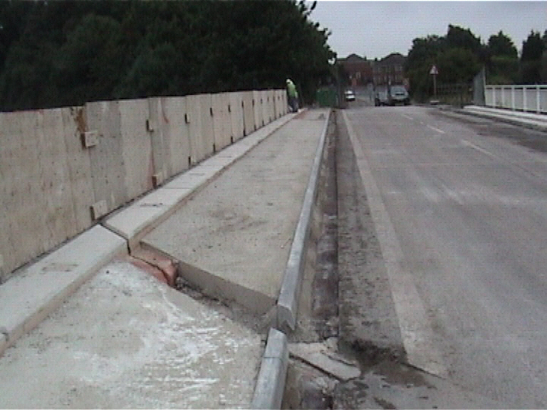
Footpath concreted and Joint bays Stripped out.
Footpath concrete overlaid with 35mm thick wearing course.
On the 15th August 05 - USL started installation of the new bridge expansion joints, due to programming issues on other sites USL had available four bridge jointing teams who spread out over the bridge and started the installation works. Due to problems with the concrete exposed when the joints areas were opened up the expansion joints were not completed until the 24th August 05 with the rubber inserts being installed into the carrier rails.
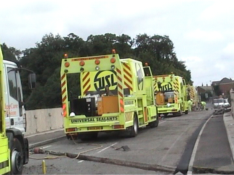
USL installing the bridge joints.
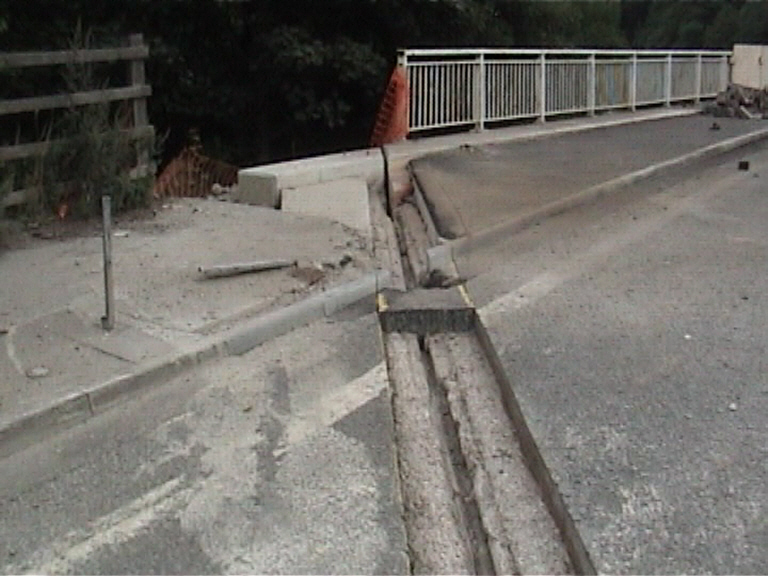
Typical joint being formed with the old joint being removed - note concrete surface, which was found to be in a poor state of repair and required extensive remedial works prior to the new joint being installed.
With the bridge deck finally clear Balmer Lindley started erection of the Aluminium parapets setting up the posts and installing the rails on boths sides of the structure. The North parapet was completed on the 24th August with the Southern Parpet being erected and set to line and level the following day. With the parapet set its alignment was checked by the designers and the posts fully grouted.
Aluminium N2 parapets being installed by Balmer Lindley.
Parpets installed and wooden hoarding removed - old parapet retained until removal in Phase II .
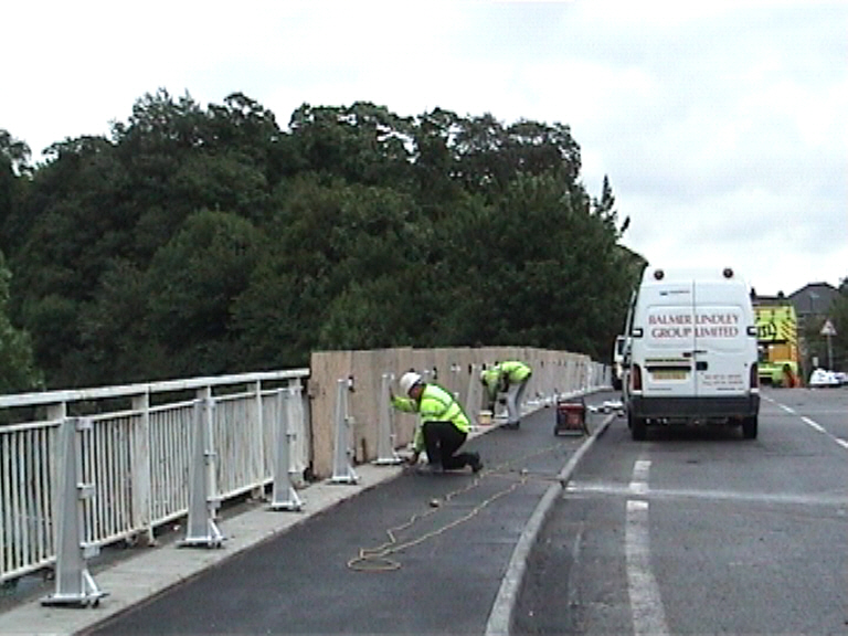
Off the deck Balmer Lindley cored out the existing anchorage posts in the footpath and grouted up the core holes in the concrete slabs - this removed the need to break out the footpath on the approach to the bridge. Balmer Lindley then installed a new safety barrier along on the approach and departure to the bridge connecting into the new parapets. Phase I works was finally completed during the first week in September 05 - with snagging works to the deck completed and temporary protection hoarding removed. The structure was finally open to traffic on the 7th Septemeber 05.
Balmer Lindley installing new safety barriers on the approach to the structure.
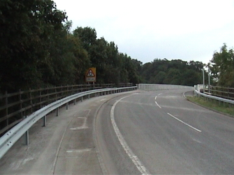
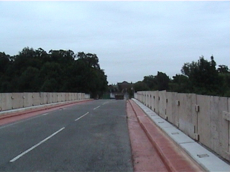
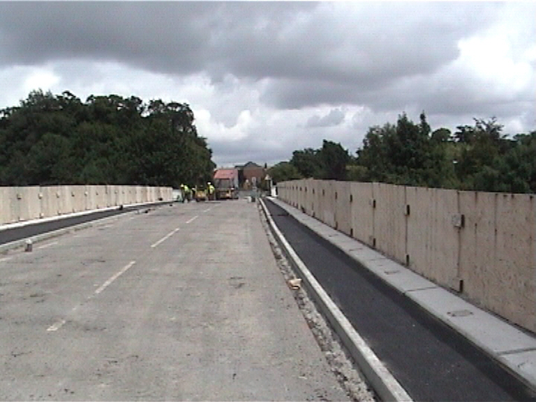
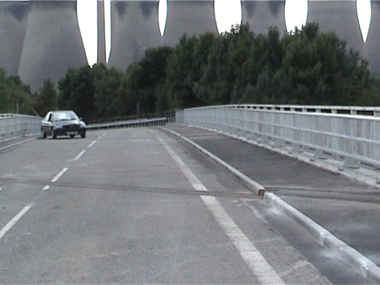
Phase I was completed at the start of Sept 2005 with the bridge being opened to traffic on the 7th September 2005.
Phase II - Full closure of the A1M below the structure following completion of Phase I works and diversion of traffic on to the newly constructed Ferrybridge to Hookmoor section 1 (Darrington to Fairburn) of the A1 on the 15th Jan 2006. The programmed three month full closure, provided access to enable the structure to have additional plan bracing installed and to enable it to be fully repainted following grit blasting and primer application. The paint protection system had broken down extensively on the steel beams and was found to be long over due for major refurbishment. It also enabled works to be undertaken to repair area of spalling to east and west abutments, remedial works to cracks in the trimmer beams and areas of spalling to cantilever parapets.
Phase II works commenced on the 16th Jan 2006 with the safety barriers being removed in front of the piers. Briton Fabrictors Ltd (Briton's) won the contract to refurbish the structure with Alfred Bagnall (Bagnall's) carrying out the grit blasting and painting, all access to the bridge beams was provided by South Yorkshire Scaffolding (SYS). Both Bagnall's and SYS were employed as sub-contractors to Britons on this project.
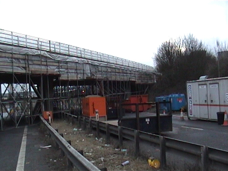
SYS started on the 17th Jan 06 erecting scaffold under the structure - prior to comming to site a design drawing had been agreed to such that the design of the scaffold was suitable to take the loads from the installation of the plan bracing and also take the loads imposed by Bagnalls carrying out the grit blasting and painting of the Girders. Initially scaffold was erected in the South bound carriageway with the North bound carriageway kept open to construction traffic working on the construction of the nearby Church Road Footbridge and refurbishing Brotherton Fox Bridge.
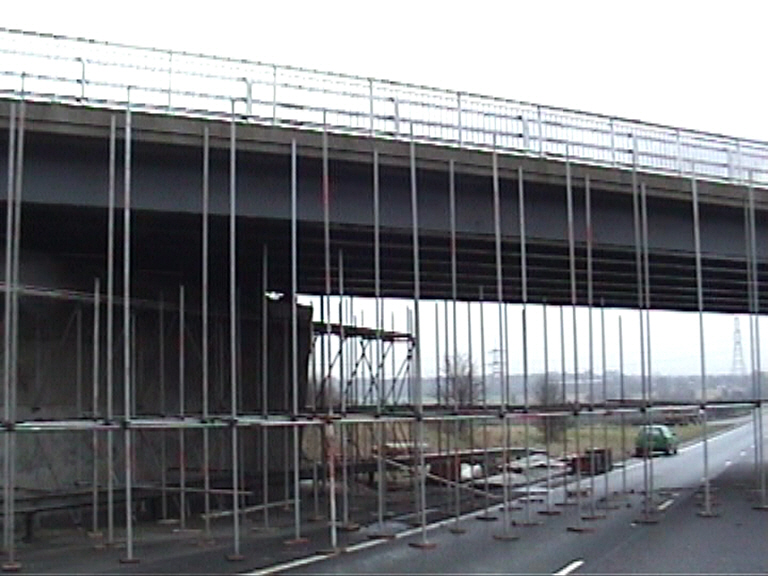
Scaffold being installed under the structure.
The first section scaffolding (East side span and south bound carriageway) was signed over to Bagnalls to start Grit blasting on the 27th Jan 2006 with SYS progressing onto the West side span and finally the North bound carriageway closing the access under the structure on the 30th Jan 2006.
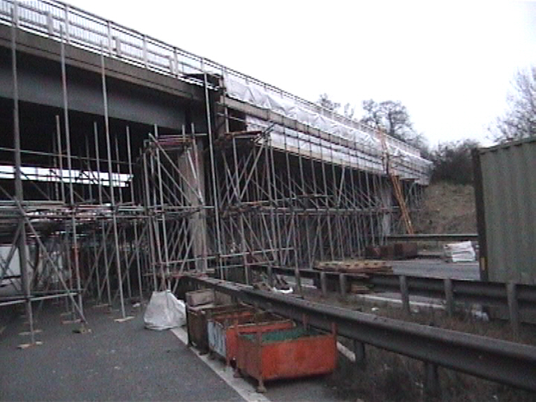
Scaffold being installed under the structure. Side sheets being installed.
Once SYS's had created a full crash deck to enable the grit blasting equipment to be installed. Bagnall's started grit blasting the bridge girders on the 30th Jan 2006, applying a holding primer to prevent the formation of rust on the face of the beams.
Scaffold crash deck being installed under the girders.
Scaffold crash deck being covered in hardboard sheeting.
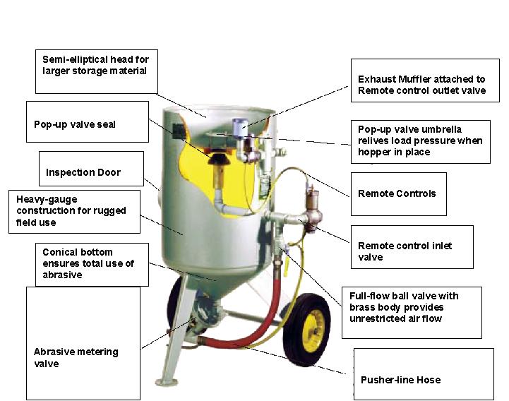
Grit Blasting is the most effective method of preparing steelwork to receive coatings. The Grit Blasting was undertaken by operatives who have received the necessary training, or are experienced and possess the required technical knowledge. As in this case there should always be a minimum of two people operating a grit blasting kit: -
a. The blaster.
b. The pot-man.
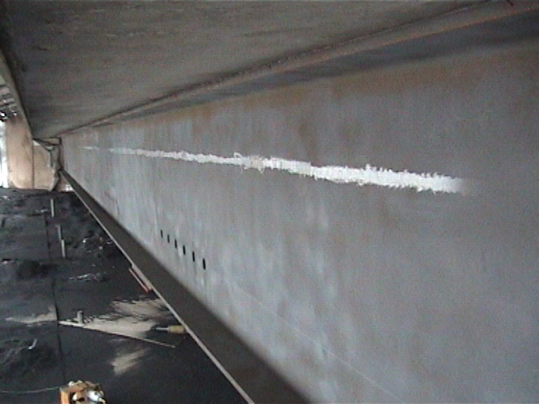
Grit Blasted outer beam - with delamination ground down to bare metal.
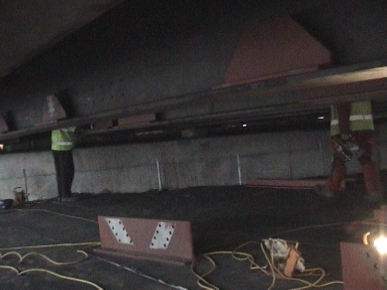
Briton Fabrication - drilling and fixing bracing angle cleats.
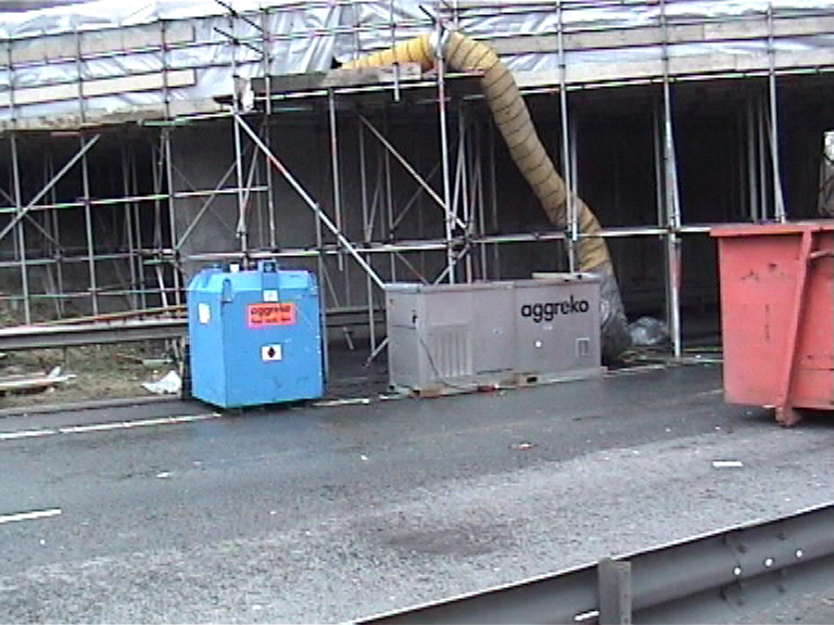
Bagnalls provided generators and hot air blowers to provide a controlled environment for painting.
During the Grit blasting it was essential that the grit build up from the blasting be kept off the crash deck to prevent the deck from being overloaded.
Bagnalls applying paint to the beams building up the coats..
The scaffold was fully enclosed with sheets the temperature control environment.
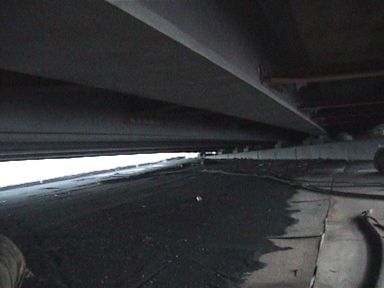
Scafffold removed as the works is completed on each span.
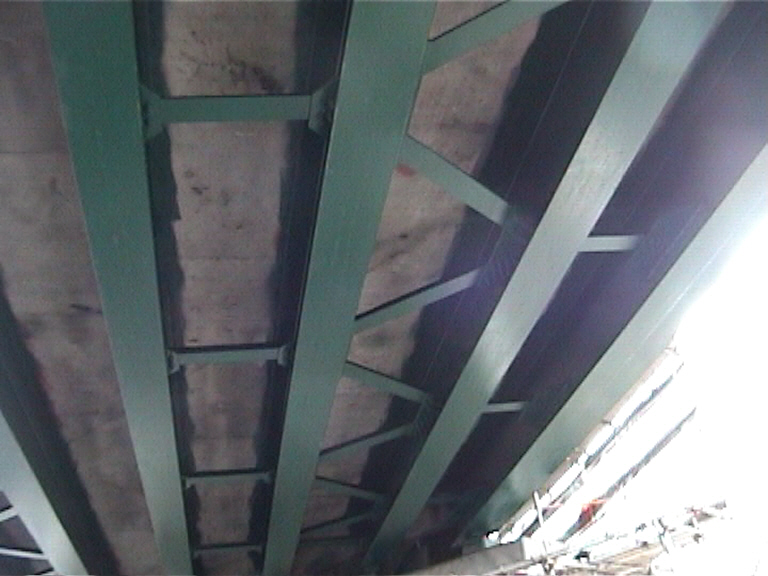
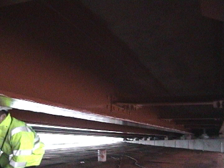
Scaffold removed showing the bracing betwen the beams.
Scaffold removed from under bridge works ongoing from MEWP to new bearings.

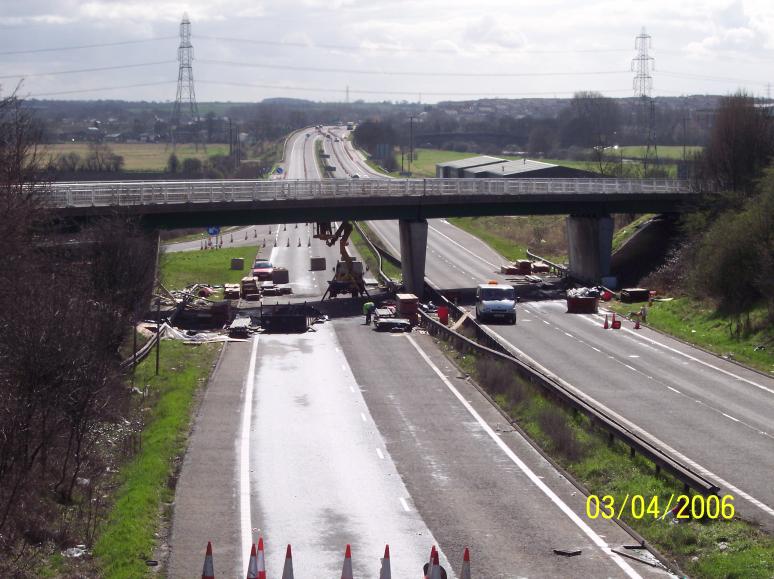
Site being cleared final tidy up to embankments ready to reopen the road (church road footbridge(s) in the back ground).
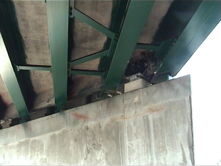
New bearings installed with steel inverted "T" connector plates drilled and fixed to the diapraghm.
Page under construction...
| 